
Specifications
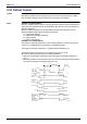
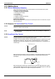
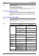
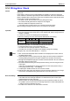
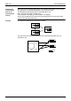
Table Of Contents
- Cover
- Table of Contents
- Part 1 List of Functions
- Part 2 Specifications
- Part 3 Printed Circuit Board Connector Wiring Diagram
- Part 4 Function and Control
- Part 5 Operation Manual
- Part 6 Service Diagnosis
- 1. Caution for Diagnosis
- 2. Problem Symptoms and Measures
- 3. Service Check Function
- 4. Code Indication on the Remote Controller
- 5. Troubleshooting
- 5.1 Indoor Units
- 5.2 Outdoor Units
- 5.3 Indoor Unit PCB Abnormality A1
- 5.4 Freeze-up Protection Control or High Pressure Control A5
- 5.5 Fan Motor or Related Abnormality A6
- 5.6 Thermistor or Related Abnormality (Indoor Unit) C4,C9
- 5.7 Front Panel Open / Close Fault C7
- 5.8 Signal Transmission Error (between Indoor and OutdoorUnit) U4
- 5.9 Unspecified Voltage (between Indoor and Outdoor Units) UA
- 5.10 Freeze-up Protection Control A5
- 5.11 Outdoor Unit PCB Abnormality E1
- 5.12 OL Activation (Compressor Overload) E5
- 5.13 Compressor Lock E6
- 5.14 DC Fan Lock E7
- 5.15 Input Over Current Detection E8
- 5.16 Discharge Pipe Temperature Control F3
- 5.17 High Pressure Control in Cooling F6
- 5.18 Compressor Sensor System Abnormality H0
- 5.19 Position Sensor Abnormality H6
- 5.20 CT or Related Abnormality H8
- 5.21 Thermistor or Related Abnormality (Outdoor Unit) P4,J3,J6,J8,J9,H9
- 5.22 Electrical Box Temperature Rise L3
- 5.23 Radiation Fin Temperature Rise L4
- 5.24 Output Over Current Detection L5
- 5.25 Insufficient Gas U0
- 5.26 Low-voltage Detection or Over-voltage Detection U2
- 5.27 Signal Transmission Error (on Outdoor Unit PCB) U7
- 5.28 Anti-icing Function in Other Rooms / UnspecifiedVoltage (between Indoor and Outdoor Units) UA,UH
- 6. Check
- Part 7 Removal Procedure
- Part 8 Others
- Part 9 Appendix
- Index
- Drawings & Flow Charts
Control Specification SiBE12-713
96 Function and Control
3.12 Malfunctions
3.12.1 Sensor Malfunction Detection
Sensor malfunction may occur either in the thermistor or current transformer (CT) system.
Relating to Thermistor Malfunction
1. Outdoor heat exchanger thermistor
2. Discharge pipe thermistor
3. Fin thermistor
4. Gas pipe thermistor
5. Outdoor air temperature thermistor
6. Liquid pipe thermistor
Relating to CT Malfunction
When the output frequency is more than 55 Hz and the input current is less than 0.5A, carry out
abnormal adjustment.
3.12.2 Detection of Overload and Over Current
Outline In order to protect the inverter, detect an excessive output current, and for protecting
compressor, monitor the OL operation.
Detail
If the OL (compressor head) temperature exceeds 130°C (2YC45), the compressor
gets interrupted.
3.12.3 Insufficient Gas Control
Outline If a power consumption is below the specified value in which the frequency is higher than the
specified frequency, it must be regarded as gas insufficient.
In addition to such conventional function, if the discharge temperature is higher than the target
discharge pipe temperature, and more than the specified temperature, and the electronic
expansion valve is fully open (450 pulses) more than the specified time, it is considered as an
insufficient gas.
With the conventional function, a power consumption is weak comparing with that in the normal
operation when gas is insufficient, and gas insufficiency is detected by checking a power
consumption.
When operating with insufficient gas, although the rise of discharge pipe temperature is great
and the electronic expansion valve is open, it is presumed as an insufficient gas if the discharge
pipe temperature is higher than the target discharge pipe temperature.
Frequency
Power consumption
Insufficient gas zone
55 Hz
(R6960)
Gas insufficient
zone
(R1391)