
Specifications

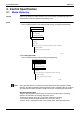
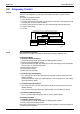
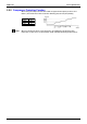
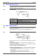
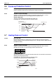
Table Of Contents
- Cover
- Table of Contents
- Part 1 List of Functions
- Part 2 Specifications
- Part 3 Printed Circuit Board Connector Wiring Diagram
- Part 4 Function and Control
- Part 5 Operation Manual
- Part 6 Service Diagnosis
- 1. Caution for Diagnosis
- 2. Problem Symptoms and Measures
- 3. Service Check Function
- 4. Code Indication on the Remote Controller
- 5. Troubleshooting
- 5.1 Indoor Units
- 5.2 Outdoor Units
- 5.3 Indoor Unit PCB Abnormality A1
- 5.4 Freeze-up Protection Control or High Pressure Control A5
- 5.5 Fan Motor or Related Abnormality A6
- 5.6 Thermistor or Related Abnormality (Indoor Unit) C4,C9
- 5.7 Front Panel Open / Close Fault C7
- 5.8 Signal Transmission Error (between Indoor and OutdoorUnit) U4
- 5.9 Unspecified Voltage (between Indoor and Outdoor Units) UA
- 5.10 Freeze-up Protection Control A5
- 5.11 Outdoor Unit PCB Abnormality E1
- 5.12 OL Activation (Compressor Overload) E5
- 5.13 Compressor Lock E6
- 5.14 DC Fan Lock E7
- 5.15 Input Over Current Detection E8
- 5.16 Discharge Pipe Temperature Control F3
- 5.17 High Pressure Control in Cooling F6
- 5.18 Compressor Sensor System Abnormality H0
- 5.19 Position Sensor Abnormality H6
- 5.20 CT or Related Abnormality H8
- 5.21 Thermistor or Related Abnormality (Outdoor Unit) P4,J3,J6,J8,J9,H9
- 5.22 Electrical Box Temperature Rise L3
- 5.23 Radiation Fin Temperature Rise L4
- 5.24 Output Over Current Detection L5
- 5.25 Insufficient Gas U0
- 5.26 Low-voltage Detection or Over-voltage Detection U2
- 5.27 Signal Transmission Error (on Outdoor Unit PCB) U7
- 5.28 Anti-icing Function in Other Rooms / UnspecifiedVoltage (between Indoor and Outdoor Units) UA,UH
- 6. Check
- Part 7 Removal Procedure
- Part 8 Others
- Part 9 Appendix
- Index
- Drawings & Flow Charts
SiBE12-713 Control Specification
Function and Control 89
3.6 Freeze-up Protection Control
Outline During cooling operation, the signals being sent from the indoor unit allow the operating
frequency limitation and then prevent freezing of the indoor heat exchanger.
Detail Conditions for Start Controlling
Judge the controlling start with the indoor heat exchanger temperature after 2 sec from
operation start and after 30 sec from changing number of operation room.
Control in Each Zone
The zone is determined by the commands from indoor units.
In drooping zone, the frequency decreases 2Hz/20 seconds.
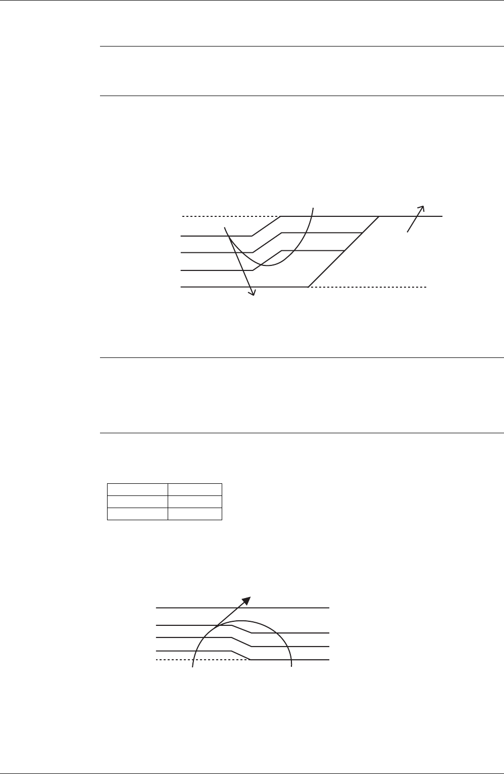
3.7 Heating Peak-cut Control
Outline Heat Pump Only
During heating operation, the signals being sent form the indoor unit allow the operating
frequency limitation and prevent abnormal high pressure. (The signal from the indoor unit must
be divided as follows.)
Detail Conditions for Start Controlling
Judge the controlling start with the indoor heat exchanger temperature after 2 min from
operation start and after A sec from changing number of operation room.
Control in Each Zone
The maximum value of heat exchange intermediate temperature of each indoor unit controls the
following (excluding stopped rooms).
In drooping zone, the frequency decreases 6Hz/40 seconds.
In up zone, the frequency increases 2Hz/60 seconds.
(R4561)
Return from stop
Reset zone
Heat exchanger
thermistor temperature
Up zone
Keep zone
Drooping zone
Stop zone
0˚C
3˚C
5˚C
7˚C
13˚C
A
30
2
When increase
When decrease
(R6034)
Reset zone
Heat exchanger
thermistor
temperature
Up zone
Keep zone
Drooping zone
Stop zone
50˚C
52˚C
54˚C
55˚C
65˚C