
Specifications


Instruction SiEBE04-507
58 System Configuration
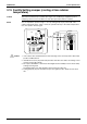
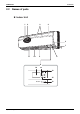
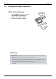
Outdoor Unit
19
22
20
21
18
17
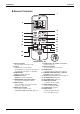
Indoor Unit
Outdoor Unit
1. Air filter
2. Titanium Apatite Photocatalytic
Air-Purifying Filter:
•
These filtersare attached to the inside of the
air filters.
3. Air inlet
4. Front panel
5. Panel tab
6. Room temperature sensor:
•
It senses the air temperature around the unit.
7. INTELLIGENT EYE sensor:
•
It detects the movements of people and
auto-matically switchesbetween normal
operation and energy saving operation.
(page 17.)
8. Display
9. Air outlet
10. Flaps (horizontal blades): (page 12.)
11. Louvers (vertical blades):
• The louversare inside of the air outlet.
(page 13.)
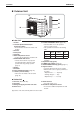
12. Indoor Unit ON/OFF switch: (page 10.)
•
Push thisswitch once to start operation.
Push once again to stop it.
•
The operation mode refers to the following
tab le.
Air flow
rate
Temperature
setting
Mode
F(C)TKS
F(C)TXS
COOL
AUTO
AUTO
AUTO
22°C
25°C
•
Thisswitch isuseful when the remote controller
is missing.
13. Operation lamp (green)
14. TIMER lamp (yellow): (page 19.)
15. INTELLIGENT EYE lamp (green):
(page 17.)
16. Signal receiver:
•
It receivessignals from the remote controller.
•
When the unit receivesasignal, you will hear a
short beep.
•
Operation start ............. beep-beep
•
Settings changed.......... beep
•
Operation stop.............. beeeeep
17. Air inlet: (Back and side)
18. Air outlet
19. Refrigerant piping and inter-unit cable
20. Drain hose
Appearance of the outdoor unit may differ from some models.
21. Earth terminal:
• It is inside of this cover.
22. Outside air temperature sensor:
• It senses the ambient temperature around
the unit.