
Specifications


Si01-406
Service Diagnosis 81
Part 6
Part 6Part 6
Part 6
Service Diagnosis
Service DiagnosisService Diagnosis
Service Diagnosis
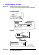
1. Troubleshooting by Lamps....................................................................82
2. Problem and Solution............................................................................83
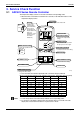
3. Service Check Function ........................................................................84
3.1 ARC423 Series Remote Controller ........................................................84
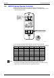
3.2 ARC433 Series Remote Controller ........................................................85
4. Troubleshooting ....................................................................................86
4.1 Error Codes ............................................................................................86
4.2 Indoor Unit PCB Abnormality .................................................................87
4.3 Freeze-up Protection Control or High Pressure Control.........................88
4.4 Fan Motor or Related Abnormality .........................................................90
4.5 Thermistor or Related Abnormality (Indoor Unit)....................................93
4.6 Indoor Unit PCB Abnormality .................................................................94
4.7 Signal Transmission Error (between Indoor and Outdoor Units)............95
4.8 OL Activation (Compressor Overload) ...................................................96
4.9 Compressor Lock ...................................................................................97
4.10 Input Over Current Detection .................................................................98
4.11 Four Way Valve Abnormality..................................................................99
4.12 High Pressure Control in Cooling .........................................................101
4.13 CT or Related Abnormality ...................................................................103
4.14 Thermistor or Related Abnormality (Outdoor Unit)...............................105
4.15 Electrical Box Temperature Rise..........................................................107
4.16 Radiation Fin Temperature Rise ..........................................................109
4.17 Output Over Current Detection.............................................................111
4.18 Insufficient Gas.....................................................................................113
5. Check ..................................................................................................115
5.1 Fan Motor Connector Output Check ....................................................115
5.2 Four Way Valve Performance Check ...................................................115
5.3 Thermistor Resistance Check ..............................................................116
5.4 Installation Condition Check.................................................................117
5.5 Discharge Pressure Check...................................................................118
5.6 Outdoor Unit Fan System Check..........................................................119
5.7 Power Supply Waveforms Check.........................................................119
5.8 Inverter Units Refrigerant System Check .............................................120
5.9 Capacitor Voltage Check......................................................................120
5.10 Power Transistor Check .......................................................................121
5.11 Hall IC Check .......................................................................................122
5.12 Power Transistor Output Check ...........................................................123
5.13 Inverter Units Compressor / Refrigerant System Check ......................124