
Specifications


Instructions Si01-406
58 System Configuration
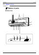
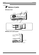
■ Outdoor Unit
■
■■
■
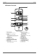
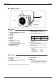
Indoor Unit
1.
Air filter
2. Air purifying filter with photocatalytic
deodorizing function:
3. Air inlet
4. Front grille
5. Grille tab
6. Display
7. Air outlet
8. Flaps (horizontal blades)
9. Louvers (vertical blades):
• The louvers are inside of the air outlet.
10. OPERATION lamp (green)
11. TIMER lamp (yellow)
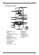
12. Indoor Unit ON/OFF switch:
•
Push this switch once to start operation.
Push once again to stop it.
•
The operation mode refers to the following
table.
•
This switch is useful when the remote controller
is missing.
13. Room temperature sensor:
•
It senses the air temperature around the unit.
14. Signal receiver:
•
It receives signals from the remote controller.
•
When the unit receives a signal, you will hear a
short beep.
•
Operation start .............beep-beep
•
Settings changed ..........beep
•
Operation stop ..............beeeeep
■
■■
■ Outdoor Unit
15. Air inlet: (Back and side)
16. Air outlet
17. Refrigerant piping and inter-unit cable
18. Drain hose
19. Earth terminal:
• It is inside of this cover.
20. Stop valve:
• Dew condensation may form on the stop
valve during operation. This does not indicate
any type of malfunction in the outdoor unit.
Appearance of the outdoor unit may differ from some models.
17
16
19
18
17
15
20
Mode
Temperature
setting
Air flow rate
COOL
22°C
AUTO