Si01-406 Инструкция по обслуживанию SPLIT Pair C-Series [Applied Models] zNon-Inverter Pair : Cooling Only zNon-Inverter Pair : Heat Pump
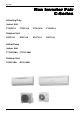
Si01-406 Non Inverter Pair C-Series zCooling Only Indoor Unit FT25CV1A FT35CV1A FT50CV1A FT60CV1A R35CV1A R50CV1A R60CV1A Outdoor Unit R25CV1A zHeat Pump Indoor Unit FTY25CVMA FTY35CVMA Outdoor Unit RY25CVMA Table of Contents RY35CVMA i
Si01-406 1. Introduction ........................................................................................... vii 1.1 Safety Cautions ...................................................................................... vii Part 1 List of Function ................................................................. 1 1. Functions.................................................................................................2 Part 2 Specifications ..................................................
Si01-406 3.8 Liquid Compression Protection Function 1 (Securing of Differential Pressure and Blown Air Temperature) ............45 3.9 Liquid Compression Protection Function 2.............................................46 3.10 Defrost Control .......................................................................................46 3.11 Insufficient Gas Control ..........................................................................47 3.12 Forced Operation Mode ...........................................
Si01-406 5.3 5.4 5.5 5.6 5.7 5.8 5.9 5.10 5.11 5.12 5.13 Thermistor Resistance Check ..............................................................116 Installation Condition Check.................................................................117 Discharge Pressure Check...................................................................118 Outdoor Unit Fan System Check..........................................................119 Power Supply Waveforms Check................................................
Si01-406 2. Wiring Diagrams..................................................................................190 2.1 Indoor Units ..........................................................................................190 2.2 Outdoor Units .......................................................................................191 Index ............................................................................................. i Drawings & Flow Charts ..................................................
Si01-406 vi Table of Contents
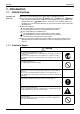
Si01-406 Introduction 1. Introduction 1.1 Safety Cautions Cautions and Warnings Be sure to read the following safety cautions before conducting repair work. The caution items are classified into “ Warning” and “ Caution”. The “ Warning” items are especially important since they can lead to death or serious injury if they are not followed closely. The “ Caution” items can also lead to serious accidents under some conditions if they are not followed.
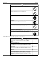
Introduction Si01-406 Caution Do not repair the electrical components with wet hands. Working on the equipment with wet hands can cause an electrical shock. Do not clean the air conditioner by splashing water. Washing the unit with water can cause an electrical shock. Be sure to provide the grounding when repairing the equipment in a humid or wet place, to avoid electrical shocks. Be sure to turn off the power switch and unplug the power cable when cleaning the equipment.
Si01-406 Introduction Warning Be sure to use the specified cable to connect between the indoor and outdoor units. Make the connections securely and route the cable properly so that there is no force pulling the cable at the connection terminals. Improper connections can cause excessive heat generation or fire. When connecting the cable between the indoor and outdoor units, make sure that the terminal cover does not lift off or dismount because of the cable.
Introduction Si01-406 Warning Do not use a joined power cable or extension cable, or share the same power outlet with other electrical appliances, since it can cause an electrical shock, excessive heat generation or fire. Caution Check to see if the parts and wires are mounted and connected properly, and if the connections at the soldered or crimped terminals are secure. Improper installation and connections can cause excessive heat generation, fire or an electrical shock.
Si01-406 Part 1 List of Function 1. Functions.................................................................................................
Functions Si01-406 — Operation Limit for Cooling (°CDB) 19.4 ~46 19.
Category Functions Inverter (with Inverter Power Control) Basic Function Compressor Comfortable Airflow Comfort Control Operation Lifestyle Convenience Functions — Operation Limit for Cooling (°CDB) 10 ~46 Operation Limit for Heating (°CWB) –10 ~20 Air Purifying Filter with Bacteriostatic, Virustatic Functions — Photocatalytic Deodorizing Filter — Air Purifying Filter with Photocatalytic Deodorizing Function { PAM Control — Oval Scroll Compressor — Swing Compressor — Titanium Apat
Functions 4 Si01-406 List of Function
Si01-406 Part 2 Specifications 1. Specifications ..........................................................................................
Specifications Si01-406 1.
Si01-406 Specifications 220-230-240V 50Hz Models Indoor Units Outdoor Units Capacity Moisture Removal Running Current Power Consumption Power Factor COP Liquid Piping Connections Gas Drain Heat Insulation Indoor Units Front Panel Color Air Flow Rate m³/min (cfm) Type Motor Output Speed Air Direction Control Air Filter Running Current Power Consumption Power Factor Temperature Control Dimensions (H×W×D) Packaged Dimensions (H×W×D) Weight Gross Weight Operation H/M/L Sound Outdoor Units Casing Color Type
Specifications Si01-406 220-230-240V 50Hz Indoor Units Models FTY25CVMA RY25CVMA Outdoor Units Capacity Moisture Removal Running Current Power Consumption Power Factor COP Liquid Piping Connections Gas Drain Heat Insulation Indoor Units Front Panel Color Air Flow Rate m³/min (cfm) Type Motor Output Speed Air Direction Control Air Filter Running Current Power Consumption Power Factor Temperature Control Dimensions (H×W×D) Packaged Dimensions (H×W×D) Weight Gross Weight Operation H/M/L Sound Outdoor Unit
Si01-406 Specifications The data on the conditions (AS/NZS3823.1) : FTY25CVMA (Rated) Capacity Running Current Power Consumption COP (Conditions) Standard AS/NZS3823.1 Specifications kW A W W/W Cooling Indoor ; 27°CDB/19°CWB Outdoor ; 35°CDB/24°CWB Cooling 2.5 5.1 960 2.60 FTY35CVMA Heating 3.4 5.6 1,090 3.12 Heating Indoor ; 20°CDB Outdoor ; 7°CDB/6°CWB Cooling 3.5 7.4 1,485 2.36 Heating 4.2 7.3 1,500 2.80 Piping Length Power Supply 7.
Specifications 10 Si01-406 Specifications
Si01-406 Part 3 Printed Circuit Board Connector Wiring Diagram 1. Printed Circuit Board Connector Wiring Diagram..................................12 1.1 1.2 1.3 1.4 FT25/35CV1A.........................................................................................12 FT50/60CV1A.........................................................................................14 FTY25/35CVMA .....................................................................................16 RY25/35CVMA ..........................
Printed Circuit Board Connector Wiring Diagram Si01-406 1. Printed Circuit Board Connector Wiring Diagram 1.
Si01-406 Printed Circuit Board Connector Wiring Diagram Control PCB Signal Receiver PCB Control PCB FU1 S1 Signal receiver PCB SW7 LED1 V1 LED2 RTH1 S27 V3 V2 5V Check FU2 S7 S21 S6 12V Check GND Printed Circuit Board Connector Wiring Diagram JC JB JA S32 S26 2P058891L 13
Printed Circuit Board Connector Wiring Diagram 1.
Si01-406 PCB Detail Printed Circuit Board Connector Wiring Diagram PCB(1): Control PCB V2 S1 V1 V3 FU1 S21 S6 JA JB JC PCB(2): Signal Receiver PCB S32 S28 S26 C : 2P099167 PCB(3): Buzzer PCB S27 SW1 S38 S29 (R2861) RTH1 (R2862) PCB(4): Display PCB LED1 LED2 S37 (R3087) Printed Circuit Board Connector Wiring Diagram 15
Printed Circuit Board Connector Wiring Diagram 1.
Si01-406 Printed Circuit Board Connector Wiring Diagram Control PCB Signal Receiver PCB FU1 S1 Control PCB SW7 LED1 Signal receiver PCB LED2 V1 RTH1 S27 S7 S21 S6 S26 JA JB JC S32 C:2P084366L Printed Circuit Board Connector Wiring Diagram 17
Printed Circuit Board Connector Wiring Diagram 1.4 Si01-406 RY25/35CVMA Connectors 1) 2) 3) 4) 5) 6) 7) Note: S10 S11 S45 S70 S80 S90 S91 Connector for PCB (2) Connector for PCB (1) (filter PCB) Connector for terminal board Connector for fan motor Connector for four way valve coil Connector for outdoor temperature thermistor / heat exchanger thermistor Connector for fin thermistor Other designations 1) V1, V2, V3 Varistor 2) FU1 Fuse (3.
Si01-406 Printed Circuit Board Connector Wiring Diagram Detail of PCB (1) V2 FU2 S10 Connect to S11 on PCB (2) V3 C:3P100242-1B Detail of PCB (2) S45 S91 FU1 V1 S11 S70 S80 S90 C:2P100238-7F Printed Circuit Board Connector Wiring Diagram 19
Printed Circuit Board Connector Wiring Diagram 20 Si01-406 Printed Circuit Board Connector Wiring Diagram
Si01-406 Part 4 Functions and Control 1. Functions of Cooling Only Models ........................................................22 1.1 1.2 1.3 1.4 1.5 1.6 1.7 1.8 1.9 1.10 1.11 1.12 1.13 Cooling Monitoring Function...................................................................22 Programme Dry Function .......................................................................23 Freeze-up Protection Control .................................................................24 Air Flow Rate Control ........
Functions of Cooling Only Models Si01-406 1. Functions of Cooling Only Models 1.1 Cooling Monitoring Function Monitoring function is activated while cooling and dry operation are suspended.
Si01-406 1.2 Functions of Cooling Only Models Programme Dry Function By the function of the microcomputer, programme dry operation reduces the humidity keeping the temperature in a minimum drop. Room temperature and air flow rate can not be controlled by the adjusting buttons because they are controlled automatically. When the programme dry function starts, dry operation is provided, and then it repeats 6-minute suspension and 4-minute dry operation alternately.
Functions of Cooling Only Models 1.3 Si01-406 Freeze-up Protection Control When the indoor heat exchanger temperature falls below 3°C in cooling or in dry operation, the compressor and the outdoor fan are forced to turn OFF. the indoor fan rotates at the L tap (in cooling operation) or LL tap (in dry operation). Note that this function is not activated for 6 minutes after compressor turns ON. When the indoor heat exchanger reaches 13 °C, the compressor and the outdoor fan restart the operations.
Si01-406 1.4 Functions of Cooling Only Models Air Flow Rate Control In cooling operation, if automatic setting has been selected for air flow rate, the wind flow is determined according to the room temperature and the set temperature. M +2.0˚C M +1.0˚C Set temperature 1.5 ML M L +2.5˚C Difference between room +1.
Functions of Cooling Only Models 1.6 Si01-406 Signal Receiving Sign When the indoor unit receives a signal from the remote controller, the unit emits a signal receiving sound. 1.7 ON / OFF Button on Indoor Unit The unit can be turned ON by the button on the front panel. This is convenient when the remote controller cannot be found or when the batteries are exhausted. Press the button again to turn the unit OFF. The unit runs as follows. 1.
Si01-406 1.9 Functions of Cooling Only Models Night Set Mode This mode automatically keeps temperature slightly higher than the temperature setting. In this way, there is no need to worry about overcooling while sleeping, and it also saves on electricity. Set the OFF timer. The unit will cool the room at the set temperature for 1 hour from when the timer starts counting. After that, the unit will raise temperature 0.5°C higher than the set temperature and cool for 30 minutes.
Functions of Cooling Only Models Si01-406 1.12 Auto-restart Function Note: Store Data If there is a power cut when the unit is operating, it will automatically resume the same operating mode when the power is restored. It takes 3 minutes to restart the operation because the 3-minute standby function is activated. Power ON/OFF Operation mode Set temperature Fan operation mode Swing ON/OFF Flap angle ON/OFF Timer 1.
Si01-406 Functions of Heat Pump Models 2. Functions of Heat Pump Models 2.1 Frequency Principle Main Control Parameters The compressor is frequency-controlled during normal operation.
Functions of Heat Pump Models Inverter Features Si01-406 The inverter provides the following features: The regulating capacity can be changed according to the changes in the outdoor air temperature and cooling / heating load. Quick heating and quick cooling The compressor rotational speed is increased when starting the heating (or cooling). This enables a quick set temperature.
Si01-406 2.2 Functions of Heat Pump Models Power-Airflow Dual Flaps, Wide-Angle Louvers and Auto-Swing Power-Airflow Dual Flaps The large flaps send a large volume of air downwards to the floor. The flap provides an optimum control area in cooling, heating and dry mode. Heating Mode During heating mode, the large flap enables direct warm air straight downwards. The flap presses the warm air above the floor to reach the entire room.
Functions of Heat Pump Models 2.3 Si01-406 Fan Speed Control for Indoor Units Control Mode The air flow rate can be automatically controlled depending on the difference between the set temperature and the room temperature. This is done through phase control and Hall IC control. For more information about Hall IC, refer to troubleshooting for fan motor on page 90. Phase Steps Phase control and fan speed control contains 8 steps: LLL, LL, L, ML, M, MH, H and HH.
Si01-406 2.4 Functions of Heat Pump Models Programme Dry Function Programme dry function removes humidity while preventing the room temperature from lowering. Since the microcomputer controls both the temperature and air flow volume, the temperature adjustment and fan adjustment buttons are inoperable in this mode. In Case of Inverter Units The microcomputer automatically sets the temperature and fan settings.
Functions of Heat Pump Models 2.5 Si01-406 Automatic Operation Automatic Cooling / Heating Function (Heat Pump Only) When the AUTO mode is selected with the remote controller, the microcomputer automatically determines the operation mode from cooling and heating according to the room temperature and setting temperature at the time of the operation startup, and automatically operates in that mode.
Si01-406 2.6 Functions of Heat Pump Models Night Set Mode When the OFF timer is set, the Night Set circuit automatically activates. The Night Set circuit maintains the airflow setting made by users. The Night Set Circuit The Night Set circuit continues heating or cooling the room at the set temperature for the first one hour, then automatically raises the temperature setting slightly in the case of heating, or lowers it slightly in the case of cooling, for economical operations.
Functions of Heat Pump Models 2.7 Si01-406 Powerful Operation Outline In order to exploit the cooling and heating capacity to full extent, operate the air conditioner by increasing the indoor fan rotating speed. Details of the Control When Powerful button is pushed in each operation mode, the fan speed / setting temperature will be converted to the following states in a period of twenty minutes.
Si01-406 2.8 Functions of Heat Pump Models Other Functions 2.8.1 Hot Start Function Heat Pump Only In order to prevent the cold air blast that normally comes when heating is started, the temperature of the heat exchanger of the indoor unit is detected, and either the air flow is stopped or is made very weak thereby carrying out comfortable heating of the room. *The cold air blast is also prevented using a similar control when the defrosting operation is started or when the thermostat gets turned ON. 2.
Functions of Heat Pump Models 2.9 Si01-406 Function of Thermistor 2.9.1 Heat Pump Model A B Four way valve Compressor (R3070) A Outdoor Heat Exchanger Thermistor (DCB) 1. The outdoor heat exchanger thermistor is used for high pressure protection during cooling operation. B Indoor Heat Exchanger Thermistor (DCN) 1. The indoor heat exchanger thermistor is used to prevent freezing.
Si01-406 Control for Heat Pump Models 3. Control for Heat Pump Models 3.1 Mode Hierarchy Outline There are two modes; the mode selected in user’s place (normal air conditioning mode) and forced operation mode for installation and providing service.
Control for Heat Pump Models 3.2 Outline Si01-406 Frequency Control Frequency will be determined according to the difference between room and set temperature. The function is explained as follows. 1. How to determine frequency. 2. Frequency command from an indoor unit. (The difference between a room temperature and the temperature set by the remote controller.) 3. Frequency command from an indoor unit. 4. Frequency initial setting. 5. PI control.
Si01-406 Control for Heat Pump Models Indoor Frequency Command (∆D signal) The difference between a room temperature and the temperature set by the remote controller will be taken as the “∆D signal” and is used for frequency command. Temperature difference ∆D signal Temperature difference ∆D signal Temperature difference ∆D signal Temperature difference ∆D signal 0 2.0 4 4.0 8 6.0 C 0.5 ∗Th OFF 1 2.5 5 4.5 9 6.5 D 1.0 1.5 2 3 3.0 3.5 6 7 5.0 5.5 A B 7.0 7.
Control for Heat Pump Models 3.3 Si01-406 Controls at Mode Changing / Start-up 3.3.1 Preheating Operation Outline Operate the inverter in the open phase with the conditions including the preheating command (only for heat pump model) from the indoor, the outdoor air temperature . Detail Preheating ON Condition When outdoor air temperature is below 11.5°C, inverter in open phase operation starts. OFF Condition When outdoor air temperature is higher than 13.
Si01-406 3.4 Control for Heat Pump Models Input Current Control Outline Detect an input current by the CT during the compressor is running, and set the frequency upper limit from such input current. In case of heat pump model, this control is the upper limit control function of the frequency which takes priority of the lower limit of four way valve activating guarantee. Detail The frequency control will be made within the following zones. When a “stop current” continues for 2.
Control for Heat Pump Models 3.6 Si01-406 Heating Peak-cut Control Outline Heat Pump Only During heating operation, the signals being sent from the indoor unit allow the operating frequency limitation and prevent abnormal high pressure. (The signal from the indoor unit must be divided as follows.) Detail Conditions for Start Controlling Judge the controlling start with the indoor heat exchanger temperature after 2 sec. from operation start.
Si01-406 3.8 Control for Heat Pump Models Liquid Compression Protection Function 1 (Securing of Differential Pressure and Blown Air Temperature) Outline To secure the reliability of the compressor (for dryness of suction refrigerant and differential pressure) which is the primary purpose of the compressor, the lower limit of the output frequency is limited to two stages under the condition of outside air temperature.
Control for Heat Pump Models 3.9 Si01-406 Liquid Compression Protection Function 2 Outline In order to obtain the dependability of the compressor, the compressor must be stopped according to the conditions of the temperature of the outdoor air and outdoor heat exchanger. Detail Operation stop depending on the outdoor air temperature Compressor operation turns OFF under the conditions that the system is in cooling operation and outdoor air temperature is below 0°C. 3.
Si01-406 Control for Heat Pump Models 3.11 Insufficient Gas Control Outline If a power consumption is below the specified value in which the frequency is higher than the specified frequency, it must be regarded as gas insufficient. Power consumption Insufficient gas zone 62 Hz Frequency (R4122) With the conventional function, a power consumption is weak comparing with that in the normal operation when gas is insufficient, and gas insufficiency is detected by checking a power consumption.
Control for Heat Pump Models Si01-406 3.12 Forced Operation Mode Outline Forced operating mode includes only forced cooling. Detail Forced Cooling Item Forced operation allowing conditions Starting/adjustment Forced Cooling 1) The outdoor unit is not abnormal and not in the 3-minute stand-by mode. 2) The operating mode of the outdoor unit is the stop mode. 3) The forced operation is ON. The forced operation is allowed when the above “and” conditions are met.
Si01-406 Part 5 System Configuration 1. System Configuration............................................................................50 2. Instructions............................................................................................51 2.1 2.2 2.3 2.4 2.5 2.6 2.7 2.8 2.9 2.10 System Configuration Manual Contents by Models...................................................................51 Safety Precautions .................................................................................
System Configuration Si01-406 1. System Configuration After the installation and test operation of the room air conditioner have been completed, it should be operated and handled as described below. Every user would like to know the correct method of operation of the room air conditioner, to check if it is capable of cooling (or heating) well, and to know a clever method of using it.
Si01-406 Instructions 2. Instructions 2.
Instructions 2.2 Si01-406 Safety Precautions Safety precautions • • • • Keep this manual where the operator can easily find them. Read this manual attentively before starting up the unit. For safety reason the operator must read the following cautions carefully. This manual classifies precautions into WARNINGS and CAUTIONS. Be sure to follow all precautions below: they are all important for ensuring safety.
Si01-406 Instructions • Do not stand or sit on the outdoor unit. Do not place any object on the unit to avoid injury, do not remove the fan guard. • Do not place anything under the indoor or outdoor unit that must be kept away from moisture. In certain conditions, moisture in the air may condense and drip. • After a long use, check the unit stand and fittings for damage. • Do not touch the air inlet and aluminum fins of outdoor unit. It may cause injury.
Instructions 2.
Si01-406 Instructions ■ Outdoor Unit 15 20 17 18 19 16 ■ Indoor Unit 1. Air filter 2. Air purifying filter with photocatalytic deodorizing function: • These filters are attached to the inside of the air filters. 11. Indoor Unit ON/OFF switch: • Push this switch once to start operation. Push once again to stop it. • The operation mode refers to the following table. 3. Air inlet Mode 4. Front grille COOL 5. Grille tab 6. Room temperature sensor: • It senses the air temperature around the unit. 7.
Instructions Si01-406 ■ Remote Controller 1 ON 2 C AMPM AMPM 4 ON/OFF POWERFUL TEMP 5 3 6 MODE 9 ON 11 OFF FAN SWING CANCEL 7 8 12 13 TIMER 10 1. Signal transmitter: • It sends signals to the indoor unit. 2. Display: • It displays the current settings. (In this illustration, each section is shown with all its displays ON for the purpose of explanation.) 3. POWERFUL button: for POWERFUL operation 4. TEMPERATURE adjustment button: • It changes the temperature setting. 5.
Si01-406 Instructions FT50/60CV1A Names of parts ■ Indoor Unit 4 5 3 1 2 8 9 7 6 10 11 12 ■ Main unit control panel 14 13 System Configuration 57
Instructions Si01-406 ■ Outdoor Unit 15 17 16 19 18 20 ■ Indoor Unit 1. Air filter 2. Air purifying filter with photocatalytic deodorizing function: 3. Air inlet 4. Front grille 12. Indoor Unit ON/OFF switch: • Push this switch once to start operation. Push once again to stop it. • The operation mode refers to the following table. 5. Grille tab Mode 6. Display COOL 7. Air outlet Air flow rate AUTO • This switch is useful when the remote controller is missing. 8. Flaps (horizontal blades) 9.
Si01-406 Instructions ■ Remote Controller 1 ON 2 C 4 ON/OFF POWERFUL TEMP 6 MODE FAN 9 ON 5 3 7 8 SWING SWING CANCEL 12 13 OFF TIMER 11 10 < ARC433A24 > 1. Signal transmitter: • It sends signals to the indoor unit. 2. Display: • It displays the current settings. (In this illustration, each section is shown with all its displays ON for the purpose of explanation.) 3. POWERFUL button: for POWERFUL operation 4. TEMPERATURE adjustment button: • It changes the temperature setting. 5.
Instructions Si01-406 FTY25/35CVMA Names of parts ■ Indoor Unit 1 2 3 4 5 6 10 9 8 7 11 12 13 14 ON OFF 60 System Configuration
Si01-406 Instructions ■ Outdoor Unit 15 20 17 18 19 16 ■ Indoor Unit 1. Air filter 2. Air purifying filter with photocatalytic deodorizing function: • These filters are attached to the inside of the air filters. 11. Indoor Unit ON/OFF switch: • Push this switch once to start operation. Push once again to stop it. • The operation mode refers to the following table. 3. Air inlet Mode 4. Front grille AUTO 5. Grille tab 6. Room temperature sensor: • It senses the air temperature around the unit. 7.
Instructions Si01-406 ■ Remote Controller 1 ON 2 C 4 HOME LEAVE ON/OFF POWERFUL TEMP 6 MODE SILENT FAN 9 ON 5 3 SWING SENSOR CANCEL 7 8 12 13 OFF TIMER 11 10 < ARC433A27 > 1. Signal transmitter: • It sends signals to the indoor unit. 2. Display: • It displays the current settings. (In this illustration, each section is shown with all its displays ON for the purpose of explanation.) 3. POWERFUL button: for POWERFUL operation 4.
Si01-406 2.4 Instructions Preparation before Operation Preparation Before Operation ■ To set the batteries 1. Press with a finger and slide the front cover to take it off. Position + and – correctly! 2 – + + 2. Set two dry batteries (AAA). – 3. Set the front cover as before. 3 1 ATTENTION ■ About batteries • When replacing the batteries, use batteries of the same type, and replace the two old batteries together. • When the system is not used for a long time, take the batteries out.
Instructions Si01-406 Preparation Before Operation ■ To operate the remote controller • To use the remote controller, aim the transmitter at the indoor unit. If there is anything to block signals between the unit and the remote controller, such as a curtain, the unit will not operate. • Do not drop the remote controller. Do not get it wet. • The maximum distance for communication is about 7 m. Receiver ■ To fix the remote controller holder on the wall 1.
Si01-406 Instructions ■ To set the clock 1. Press “CLOCK button”. is displayed. C blinks. 2. Press “TIMER setting button” to set the clock to the present time. Holding down “ ” or “ ” button rapidly increases or decreases the time display. 3. Press “CLOCK button”. blinks. HOME LEAVE ON/OFF POWERFUL TEMP MODE SILENT FAN SWING SENSOR 2 ON ■ Turn the breaker ON • Turning ON the breaker opens the flap, then closes it again. (This is a normal procedure.
Instructions 2.5 Si01-406 AUTO • DRY • COOL • HEAT • FAN Operation AUTO · DRY · COOL · HEAT · FAN Operation The air conditioner operates with the operation mode of your choice. From the next time on, the air conditioner will operate with the same operation mode. ■ To start operation C 1. Press “MODE selector button” and select a operation mode. • Each pressing of the button advances the mode setting in sequence.
Si01-406 Instructions ■ To change the air flow rate setting 5. Press “FAN setting button”. DRY mode AUTO or COOL or HEAT or FAN mode Five levels of air flow rate setting from “ The air flow rate setting is not variable. plus “ ” to “ ” ” are available. NOTE ■ Note on HEAT operation • Since this air conditioner heats the room by taking heat from outdoor air to indoors, the heating capacity becomes smaller in lower outdoor temperatures.
Instructions 2.6 Si01-406 Adjusting the Air Flow Direction Adjusting the Air Flow Direction You can adjust the air flow direction to increase your comfort. ■ To adjust the horizontal blades (flaps) ON C 1. Press “SWING button”. • “ ” is displayed on the LCD. 2. When the flaps have reached the desired position, press “SWING button” once more. HOME LEAVE ON/OFF POWERFUL TEMP MODE SILENT FAN The flaps will stop moving.
Si01-406 2.7 Instructions POWERFUL Operation POWERFUL Operation POWERFUL operation quickly maximizes the effect in any of the operation modes. Using POWERFUL operation you will get always the maximum efficiency. ■ To start POWERFUL operation ON 1. Press “POWERFUL button”. • POWERFUL operation ends in 20 minutes. Then the system automatically operates again with the settings which were used before POWERFUL operation. • When using POWERFUL operation, there are some functions which are not available.
Instructions 2.8 Si01-406 TIMER Operation TIMER Operation Timer functions are useful for automatically switching the air conditioner on or off at night or in the morning. You can also use OFF TIMER and ON TIMER in combination. ■ To use OFF TIMER operation C • Check that the clock is correct. If not, set the clock to the present time. (page 9.) 1. Press “OFF TIMER button”. is displayed. HOME LEAVE ON/OFF POWERFUL TEMP MODE SILENT FAN blinks. 2.
Si01-406 Instructions ■ To use ON TIMER operation • Check that the clock is correct. If not, set the clock to the present time (page 9.). 1. Press “ON TIMER button”. is displayed. C blinks. 2. Press “TIMER Setting button” until the time setting reaches the point you like. • Every pressing of either button increases or decreases the time setting by 10 minutes. Holding down either button changes the setting rapidly. 3. Press “ON TIMER button” again.
Instructions 2.9 Si01-406 Care and Cleaning FT25/35CV1A, FTY25/35CVMA Care and Cleaning CAUTION Before cleaning, be sure to stop the operation and turn the breaker OFF. Units ■ Indoor unit, Outdoor unit and Remote controller 1. Wipe them with dry soft cloth. ■ Front grille 1. Open the front grille. • Hold the grille by the tabs on the two sides and lift it unitl it stops with a click. 2. Remove the front grille.
Si01-406 Instructions Filters 1. Open the front grille. 2. Pull out the air filters. • Push a little upwards the tab at the center of each air filter, then pull it down. 3. Take off the air purifying filter with photocatalytic deodorizing function. Air purifying filter with photocatalytic deodorizing function • Hold the recessed parts of the frame and unhook the four claws. Air filter 4. Clean or replace each filter. See below. 5.
Instructions Si01-406 Check Check that the base, stand and other fittings of the outdoor unit are not decayed or corroded. Check that nothing blocks the air inlets and the outlets of the indoor unit and the outdoor unit. Check that the drain comes smoothly out of the drain hose during COOL or DRY operation. • If no drain water is seen, water may be leaking from the indoor unit. Stop operation and consult the service shop if this is the case. ■ Before a long idle period 1.
Si01-406 Instructions FT50/60CV1A Care and Cleaning CAUTION Before cleaning, be sure to stop the operation and turn the breaker OFF. Units ■ Indoor unit, Outdoor unit and Remote controller 1. Wipe them with dry soft cloth. ■ Front grille 1. Open the front grille. • Hold the grille by the tabs on the two sides and lift it until it stops with a click. 2. Remove the front grille. • Open the front panel further while sliding it to either the left or right and pulling it toward you.
Instructions Si01-406 Filters 1. Open the front grille. 2. Pull out the air filters. • Push a little upwards the tab at the center of each air filter, then pull it down. 3. Take off the air purifying filter with photocatalytic deodorizing function. • Press the top of the air-cleaning filter onto the tabs (3 tabs at top). Then press the bottom of the filter up slightly, and press it onto the tabs (3 at bottom). tabs (3 tabs at top) tabs (3 at bottom) 4. Clean or replace each filter. See below. 5.
Si01-406 Instructions Check Check that the base, stand and other fittings of the outdoor unit are not decayed or corroded. Check that nothing blocks the air inlets and the outlets of the indoor unit and the outdoor unit. Check that the drain comes smoothly out of the drain hose during COOL or DRY operation. • If no drain water is seen, water may be leaking from the indoor unit. Stop operation and consult the service shop if this is the case. ■ Before a long idle period 1.
Instructions Si01-406 2.10 Troubleshooting Trouble Shooting These cases are not troubles. The following cases are not air conditioner troubles but have some reasons. You may just continue using it. Case Explanation Operation does not start soon. • When ON/OFF button was pressed soon after operation was stopped. • When the mode was reselected. • This is to protect the air conditioner. You should wait for about 3 minutes. Hot air does not flow out soon after the start of heating operation.
Si01-406 Instructions Check again. Please check again before calling a repair person. Case The air conditioner does not operate. (OPERATION lamp is off) Check • Hasn’t a breaker turned OFF or a fuse blown? • Isn’t it a power failure? • Are batteries set in the remote controller? • Is the timer setting correct? Cooling (Heating) effect is poor.
Instructions Si01-406 Call the service shop immediately. WARNING ■ When an abnormality (such as a burning smell) occurs, stop operation and turn the breaker OFF. Continued operation in an abnormal condition may result in troubles, electric shocks or fire. Consult the service shop where you bought the air conditioner. ■Do not attempt to repair or modify the air conditioner by yourself. Incorrect work may result in electric shocks or fire. Consult the service shop where you bought the air conditioner.
Si01-406 Part 6 Service Diagnosis 1. Troubleshooting by Lamps....................................................................82 2. Problem and Solution............................................................................83 3. Service Check Function ........................................................................84 3.1 ARC423 Series Remote Controller ........................................................84 3.2 ARC433 Series Remote Controller .............................................
Troubleshooting by Lamps Si01-406 1. Troubleshooting by Lamps Operation Lamp The operation lamp flashes when any of the following errors is detected. 1. When a protection device of the indoor or outdoor unit is activated or when the thermistor malfunctions, disabling equipment operation. 2. When a signal transmission error occurs between the indoor and outdoor units. In either case, conduct the diagnostic procedure described in the following pages.
Si01-406 Problem and Solution 2. Problem and Solution Problem Check None of the units operates. Check the power supply. Check the type of the indoor units. Check the outdoor air temperature. Diagnosis with remote controller indication Check the remote controller addresses. Operation sometimes stops. Check the power supply. Check the outdoor air temperature. Diagnosis with remote controller indication Equipment operates but does not cool, or does not heat (only for heat pump model).
Service Check Function Si01-406 3. Service Check Function 3.1 ARC423 Series Remote Controller The temperature display sections on the main unit indicate corresponding codes. 1. When the timer cancel button is held down for 5 seconds, a “00” indication flashes on the temperature display section. Transmitter Display It sends signals to the indoor unit. It displays the current settings. (In this illustration, each section is shown with all its displays ON for the purpose of explanation.
Si01-406 3.2 Service Check Function ARC433 Series Remote Controller The temperature display sections on the main unit indicate corresponding codes. 1. When the timer cancel button is held down for 5 seconds, a “00” indication flashes on the temperature display section. ON C ON/OFF POWERFUL TEMP MODE FAN ON CANCEL TIMER CANCEL button It cancels the timer setting. OFF TIMER (R4114) 2. Press the timer cancel button repeatedly until a continuous beep is produced.
Troubleshooting Si01-406 4. Troubleshooting 4.
Si01-406 4.2 Troubleshooting Indoor Unit PCB Abnormality (A1) Remote Controller Display A1 Method of Malfunction Detection Evaluation of zero-cross detection of power supply by indoor unit. Malfunction Decision Conditions When there is no zero-cross detection in approximately 10 continuous seconds.
Troubleshooting 4.3 Si01-406 Freeze-up Protection Control or High Pressure Control (A5) Remote Controller Display A5 Method of Malfunction Detection High pressure control (heat pump model only) Malfunction Decision Conditions High pressure control Supposed Causes 88 During heating operations, the temperature detected by the indoor heat exchanger thermistor is used for the high pressure control (stop, outdoor fan stop, etc.
Si01-406 Troubleshooting Troubleshooting Caution Check No.6 Refer to P.116 Be sure to turn off power switch before connect or disconnect connector, or parts damage may be occurred. Check the air passage. Is there any short-circuit? YES Provide sufficient air passage. NO Check the intake air filter. Is it very dirty? YES Clean the air filter. NO Check the dust accumulation on the indoor unit heat exchanger. Is it very dirty? YES Clean the heat exchanger. NO Check No.
Troubleshooting 4.4 Si01-406 Fan Motor or Related Abnormality(A6) 4.4.1 AC motor (FT25/35CV1A, FTY25/35CVMA) Remote Controller Display A6 Method of Malfunction Detection The rotation speed detected by the Hall IC during fan motor operation is used to determine abnormal fan motor operation. Malfunction Decision Conditions When the detected rotation speed is less than 50% of the HH tap under maximum fan motor rotation demand.
Si01-406 Troubleshooting 4.4.2 DC Motor (FT50/60CV1A) Remote Controller Display A6 Method of Malfunction Detection The rotation speed detected by the Hall IC during fan motor operation is used to determine abnormal fan motor operation. Malfunction Decision Conditions When the detected rotation speed is less than 50% of the H tap under maximum fan motor rotation demand. Supposed Causes Service Diagnosis Operation halt due to short circuit inside the fan motor winding.
Troubleshooting Si01-406 Troubleshooting Caution Check No.01 Refer to P.115 Be sure to turn off power switch before connect or disconnect connector, or parts damage may be occurred. Turn off power supply and rotate fan by hand. Does fan rotate smoothly? NO Replace fan motor. YES Turn power ON and operate fan. Does it rotate? Turn off power supply NO and disconnect fan motor connector, then turn power ON. YES Check No.
Si01-406 4.5 Troubleshooting Thermistor or Related Abnormality (Indoor Unit) (C4,C9) Remote Controller Display C4, C9 Method of Malfunction Detection The temperatures detected by the thermistors are used to determine thermistor errors. Malfunction Decision Conditions When the thermistor input is more than 4.96 V or less than 0.04 V during compressor operation∗. ∗ (reference) When above about 212°C(less than 120 ohms) or below about –50°C (more than 1,860 kohms).
Troubleshooting 4.6 Si01-406 Indoor Unit PCB Abnormality Remote Controller Display ∗ Method of Malfunction Detection The proper programme operation of the microcomputer is checked by the programme. Malfunction Decision Conditions When the microcomputer programme does not function properly. Supposed Causes Microcomputer programme is in abnormal condition due to an external factor. *Noise *Momentary voltage drop. *Momentary power failure, etc. Faulty indoor unit PCB.
Si01-406 4.7 Troubleshooting Signal Transmission Error (between Indoor and Outdoor Units) (U4) Remote Controller Display U4 Method of Malfunction Detection The data received from the outdoor unit in indoor unit-outdoor unit signal transmission is checked whether it is normal. Malfunction Decision Conditions When the data sent from the outdoor unit cannot be received normally, or when the content of the data is abnormal. Supposed Causes Faulty outdoor unit PCB. Faulty indoor unit PCB.
Troubleshooting 4.8 Si01-406 OL Activation (Compressor Overload) (E5) Remote Controller Display E5 Method of Malfunction Detection A compressor overload is detected through compressor OL. Malfunction Decision Conditions If the compressor OL is activated twice, the system will be shut down. The error counter will reset itself if this or any other error does not occur during the following 60-minute compressor running time (total time). ∗ The operating temperature condition is not specified.
Si01-406 4.9 Troubleshooting Compressor Lock (E6) Remote Controller Display E6 Method of Malfunction Detection Compressor startup errors are detected using input current detected by CT and compressor’s operation frequency. Malfunction Decision Conditions When the inlet current is over the setting value. ∗ Setting value = (145 / 256 × Output frequency) – 6 (A) When a compressor startup error is generated 16 times consecutively, the system shuts down.
Troubleshooting Si01-406 4.10 Input Over Current Detection (E8) Remote Controller Display E8 Method of Malfunction Detection An input over-current is detected by checking the input current value being detected by CT with the compressor running. Malfunction Decision Conditions The following CT input with the compressor running continues for 2.5 seconds.
Si01-406 Troubleshooting 4.11 Four Way Valve Abnormality (EA) Remote Controller Display EA Method of Malfunction Detection The indoor air temperature thermistor, the indoor unit heat exchanger thermistor, the outdoor temperature thermistor and the outdoor unit heat exchanger thermistor are checked to see if they function within their normal ranges in the operating mode. Malfunction Decision Conditions Cooling / dry operation A following condition continues over 10 minute after operating 5 minutes.
Troubleshooting Si01-406 Troubleshooting Caution Check No.5 Refer to P.115 Check No.6 Refer to P.116 Be sure to turn off power switch before connect or disconnect connector, or parts damage may be occurred. Four way valve coil disconnected (loose)? YES NO YES Harness out of connector? Check No.11 Refer to P.120 Correct. Reconnect. NO Check the continuity of the four way valve coil and harness. Disconnect the harness from the connector. Resistance between harnesses about 3kΩ±0.
Si01-406 Troubleshooting 4.12 High Pressure Control in Cooling (F6) Remote Controller Display F6 Method of Malfunction Detection High-pressure control (stop, frequency drop, etc.) is activated in the cooling mode if the temperature being sensed by the heat exchanger thermistor exceeds the limit. Malfunction Decision Conditions Activated when the temperature being sensed by the heat exchanger thermistor rises above 60°C. (Deactivated when the said temperature drops below 50°C.
Troubleshooting Si01-406 Troubleshooting Caution Check No.6 Refer to P.116 Check No.7 Refer to P.117 Be sure to turn off power switch before connect or disconnect connector, or parts damage may be occurred. Check the installation space. Check No.7 Installation condition check Abnormal Normal Check No.9 Refer to P.119 Check No.9 Outdoor fan check Abnormal Normal Change the air outlet grille position. Change the installation location. Clean the heat exchanger. Replace the fan motor.
Si01-406 Troubleshooting 4.13 CT or Related Abnormality (H8) Remote Controller Display H8 Method of Malfunction Detection A CT or related error is detected by checking the compressor running frequency and CTdetected input current. Malfunction Decision Conditions The compressor running frequency is below 62 Hz and the CT input is below 0.1 V. (The input current is also below 0.5 A.) If this error repeats 4 times, the system will be shut down.
Troubleshooting Si01-406 Troubleshooting Caution Check No.12 Refer to P.120 Be sure to turn off power switch before connect or disconnect connector, or parts damage may be occurred. Turn off the power and turn it on again. Get the system started. ∗ Running current as shown at right with relay cable 1 or 2? YES Current (guideline) NO Check No. 12 Check the capacitor voltage. Rising with increasing frequency 2 sec DC290~380V? Replace the outdoor unit PCB.
Si01-406 Troubleshooting 4.14 Thermistor or Related Abnormality (Outdoor Unit) (P4,J6,H9) Remote Controller Display P4, J6, H9 Method of Malfunction Detection This type of error is detected by checking the thermistor input voltage to the microcomputer. [A thermistor error is detected by checking the temperature.] Malfunction Decision Conditions The thermistor input is above 4.96 V or below 0.04 V with the power on.
Troubleshooting Si01-406 Troubleshooting Caution Check No.6 Refer to P.116 Be sure to turn off power switch before connect or disconnect connector, or parts damage may be occurred. Turn on the power again. Error displayed again on remote controller? NO Reconnect. YES Connector or thermistor disconnected? YES Reconnect. NO Check No. 6 Check the thermistor resistance value. NO Normal? YES Replace defective one(s) of the following thermistors.
Si01-406 Troubleshooting 4.15 Electrical Box Temperature Rise (L3) Remote Controller Display L3 Method of Malfunction Detection An electrical box temperature rise is detected by checking the radiation fin thermistor with the compressor off. Malfunction Decision Conditions With the compressor off, the radiation fin temperature is above 122°C. (Reset is made when the temperature drops below 113°C.
Troubleshooting Si01-406 Troubleshooting Caution Check No.6 Refer to P.116 Be sure to turn off power switch before connect or disconnect connector, or parts damage may be occurred. Turn off the power and turn it on again. Check No.7 Refer to P.117 Error again or outdoor unit fan activated? Check No.9 Refer to P.119 WARNING To cool down the electricals, the outdoor unit fan gets started when the radiation fin temperature rises above 120˚C and stops itself when it drops below 113˚C. YES NO Check No.
Si01-406 Troubleshooting 4.16 Radiation Fin Temperature Rise (L4) Remote Controller Display L4 Method of Malfunction Detection A radiation fin temperature rise is detected by checking the radiation fin thermistor with the compressor on. Malfunction Decision Conditions If the radiation fin temperature with the compressor on is above 81°C, If a radiation fin temperature rise takes place 4 times successively, the system will be shut down.
Troubleshooting Si01-406 Troubleshooting Check No.6 Refer to P.116 Caution Be sure to turn off power switch before connect or disconnect connector, or parts damage may be occurred. Turn off the power and turn it on again to get the system started. Check No.7 Refer to P.117 Error displayed again? Check No.9 Refer to P.119 YES NO Check No. 6 Check the thermistor resistance value. l Fin thermistor Check the radiation fin temperature.
Si01-406 Troubleshooting 4.17 Output Over Current Detection (L5) Remote Controller Display L5 Method of Malfunction Detection An output over-current is detected by checking the current that flows in the inverter DC section. Malfunction Decision Conditions A position signal error occurs while the compressor is running. A speed error occurs while the compressor is running. An output over-current input is fed from the output over-current detection circuit to the microcomputer.
Troubleshooting Si01-406 Troubleshooting Caution Check No.7 Refer to P.117 Be sure to turn off power switch before connect or disconnect connector, or parts damage may be occurred. ∗ An output over-current may result from wrong internal wiring. If the wires have been disconnected and reconnected for part replacement, for example, and the system is interrupted by an output over-current, take the following procedure. NO Stop valve fully open? Check No.8 Refer to P.118 Check No.13 Refer to P.
Si01-406 Troubleshooting 4.18 Insufficient Gas (U0) Remote Controller Display U0 Method of Malfunction Detection Gas shortage detection I : A gas shortage is detected by checking the CT-detected input current value and the compressor running frequency. Gas shortage detection II : A gas shortage is detected by checking the difference between indoor unit heat exchanger temperature and room temperature as well as the difference between outdoor unit heat exchanger temperature and room temperature.
Troubleshooting Si01-406 Troubleshooting Caution Check No.6 Refer to P.116 Be sure to turn off power switch before connect or disconnect connector, or parts damage may be occurred. Any thermistor disconnected? NO YES * Indoor / outdoor unit heat exchanger thermistor * Room temperature thermistor * Outdoor air thermistor YES Reconnect in position. Open the stop valve. Stop valve closed? NO Check for gas leakage.
Si01-406 Check 5. Check 5.1 Fan Motor Connector Output Check Check No.01 1. 2. 3. 4. 5. Check connector connection. Check motor power supply voltage output (pins 4-7). Check motor control voltage (pins 4-3). Check rotation command voltage output (pins 4-2). Check rotation pulse input (pins 4-1). S1 7 6 5 4 3 2 1 Motor power supply voltage Unused Unused P.0V (reference potential) Motor control voltage (15 VDC) Rotation command voltage (1~ 6 VDC) Rotation pulse input (R3199) 5.
Check 5.3 Si01-406 Thermistor Resistance Check Check No.6 Remove the connectors of the thermistors on the PCB, and measure the resistance of each thermistor using tester. The relationship between normal temperature and resistance is shown in the graph and the table below. Thermistor R25°C=20kΩ B=3950 116 Temperature (°C) –20 211.0 (kΩ) –15 –10 150 116.5 –5 0 88 67.2 5 10 51.9 40 15 20 31.8 25 25 30 20 16 35 40 13 10.6 45 50 8.7 7.
Si01-406 5.4 Check Installation Condition Check Check No.7 Installation condition check Check the allowable dimensions of the air suction and discharge area. Normal Does the discharged air from other outdoor unit cause an increase of the suction air temperature? Abnormal YES Change the position of the air discharge grille or the installation location. Change the position of the air discharge grille or the installation location.
Check 5.5 Si01-406 Discharge Pressure Check Check No.8 Discharge pressure check High NO Replace compessor. YES Is the stop valve open? NO Open the stop valve. YES Is the connection pipe deformed? NO Replace the pipe installed at the site. YES Are the heat exchanger and air filter dirty? Not dirty Dirty Clean. Replace the compressor.
Si01-406 5.6 Check Outdoor Unit Fan System Check Check No.9 DC motor — FT50/60CV1A Check the outdoor unit fan system. NO Outdoor unit fan running? Fan motor lead wire connector disconnected? YES YES Reconnect. NO Outdoor unit fan system functioning. Go to Check No. 15. (R2857) AC motor — FT25/35CV1A, FTY25/35CVMA Check the outdoor fan system. Does the outdoor fan rotate? NO Abnormal Check the fan motor lead wire Repair. connector for secure connection.
Check 5.8 Si01-406 Inverter Units Refrigerant System Check Check No.11 Refrigerant system check Is the discharge thermister disconnected from the holder? YES Correct the problem. NO Is any moisture found in sight glass. YES Conduct vacuum drying. Conduct the check after operating the equipment for a sufficient length of time. NO Check for gas leaks. See the section on insufficient gas detection. YES Replace the refrigerant. (R1445) 5.9 Capacitor Voltage Check Check No.
Si01-406 Check 5.10 Power Transistor Check Check No.13 Note: Check to make sure that the voltage between the terminal of Power transistor (+) and (-) is approx. 0 volt before checking power transistor. < Measuring method > Disconnect the compressor harness connector from the outdoor unit PCB. To disengage the connector, press the protrusion on the connector.
Check Si01-406 5.11 Hall IC Check Check No.16 1. Check the connector connection. 2. With the power ON, operation OFF, and the connector connected, check the following. ∗Output voltage of about 5 V between pins 1 and 3. ∗Generation of 3 pulses between pins 2 and 3 when the fan motor is operating. Failure of (1) Æ faulty PCB Æ Replace the PCB. Failure of (2) Æ faulty hall IC Æ Replace the fan motor. Both (1) and (2) result Æ Replace the PCB.
Si01-406 Check 5.12 Power Transistor Output Check Check No.17 Measure the output current and voltage of the power transistor. Output Current Measurement Remove the front panel, and measure the current in the red, yellow and blue wire harness inside the compressor using a clamp meter. 1. Attach the clamp meter to the red, yellow and blue wire harness, and conduct forced cooling operation. 2. When the output frequency has stabilized, measure the output current of each phase. 3.
Check Si01-406 5.13 Inverter Units Compressor / Refrigerant System Check Check No.18 Caution Be sure to turn off power switch before connect or disconnect connector, or parts damage may be occurred. Compressor/refrigerant system check Does the equipment stop frequency due to startup error? NO ∗ Check if there are any damage on refrigerant piping. YES Faulty compressor. Replace the compressor. To next step.
Si01-406 Part 7 Removal Procedure 1. FT25/35CV1A, FTY25/35CVMA .........................................................126 1.1 1.2 1.3 1.4 1.5 1.6 1.7 Removal of Air Filter.............................................................................126 Removal of Front Grille ........................................................................129 Removal of Horizontal Blades / Vertical Blades ...................................132 Removal of Electrical Parts Box / PCB / Swing Motor...................
FT25/35CV1A, FTY25/35CVMA Si01-406 1. FT25/35CV1A, FTY25/35CVMA 1.1 Removal of Air Filter Procedure Step Warning Be sure to wait 10 minutes or more after turning off all power supplies before disassembling work. Procedure Points 1. External features If ON/OFF button is kept pushing for 5 seconds, a forced cooling operation will be carried out for approx. 15 minutes. When the signal receiver catches a signal from the remote controller, it produces beep sound and the operation lamp blinks. 2.
Si01-406 Step Procedure 3. Remove the front panel. 1 Hook a finger onto the projection part provided on the both sides of the unit’s panel and open up the panel to the position higher than it will stop. 2 FT25/35CV1A, FTY25/35CVMA Points Support the front panel by one hand, while remove the rotation axis at the upper center by the other hand. And pull out the front panel forward to remove. Remove front panel from the unit.
FT25/35CV1A, FTY25/35CVMA Step 3 128 Si01-406 Procedure Points When restoring the air filter, make sure that the projection parts on the panel are in the guide groove, and then shut the panel.
Si01-406 1.2 FT25/35CV1A, FTY25/35CVMA Removal of Front Grille Procedure Step Warning Be sure to wait 10 minutes or more after turning off all power supplies before disassembling work. Procedure Points 1. Remove the service cover. 1 Remove a service cover mounting screw. Open service cover upward. A switch for field setting is not provided in particular.
FT25/35CV1A, FTY25/35CVMA Step Procedure 2. Remove the front grille assembly. 1 Remove the two screws, in the right and the left, which fix the main body with the front grille. 2 130 Si01-406 Disengage the two hooks on the upper part. In case that the hooks are not pressed from above, remove the front panel and then remove the grille while pushing the hook through a clearance between the front grille and the heat exchanger.
Si01-406 Step 3 FT25/35CV1A, FTY25/35CVMA Procedure The front grille can be removed in a manner to pull out the upper part forward and lift up the lower part. Removal Procedure Points When restoring the grille, Make sure whether each hook is set as it was.
FT25/35CV1A, FTY25/35CVMA 1.3 Removal of Horizontal Blades / Vertical Blades Procedure Step Warning Be sure to wait 10 minutes or more after turning off all power supplies before disassembling work. Procedure 1. Remove the horizontal blades. 1 Lift horizontal blade to open position. 2 Disengage horizontal blade from blade retaining section. 3 Bend blade slightly and remove it from the unit.
Si01-406 Step FT25/35CV1A, FTY25/35CVMA Procedure Points For restoring. 1. Since the key pattern hook is provided on the left side, insert the edge of the blade to the tip while rotating it. 2. Restore the two fixed parts of the horizontal blade onto the hook. 2. Remove the vertical blades. 1 Disengage the vertical blade’s joint from the fixed plate. 2 Remove the blade forward. Removal Procedure Five vertical blades are integrated with the joint rod. (so, only one blade can’t be exchanged.
FT25/35CV1A, FTY25/35CVMA 1.4 Si01-406 Removal of Electrical Parts Box / PCB / Swing Motor Procedure Step Warning Be sure to wait 10 minutes or more after turning off all power supplies before disassembling work. Procedure Points Remove the front grill. 1. Remove the electrical parts box. 1 Disconnect the connection wires. 2 Disconnect the connectors of fan motor (S1 and S7). Pay attention to the direction 3 4 134 Disconnect the connector of swing motor (S6).
Si01-406 Step 5 6 FT25/35CV1A, FTY25/35CVMA Procedure Remove a screw on the terminal strip. Points The electrical parts box can be removed instead of disengaging the terminal strip. Remove a screw on the electrical parts box.
FT25/35CV1A, FTY25/35CVMA Step 7 136 Si01-406 Procedure Pull up the electrical parts box forward to remove. Points A hook is provided on the behind.
Si01-406 Step FT25/35CV1A, FTY25/35CVMA Procedure Points 2. Remove the printed circuit board (PCB). 1 Remove the shelter. 2 Disengage the front plate of the electrical parts box. Disengage the knobs by pushing the two hooks at the top and the bottom. 3 Sliding to the left, the front part of the electrical parts box can be removed.
FT25/35CV1A, FTY25/35CVMA Step Procedure 4 Disengage the four knobs on the back of the signal receiver PCB.
Si01-406 Step 6 FT25/35CV1A, FTY25/35CVMA Procedure Control PCB Points The control printed circuit board is integrated with the power supply printed circuit board. 3. Remove the swing motor assembly. 1 To remove swing motor assembly, remove two screws. (Manual adjusting for the vertical blades.) Provide a supporter so that the joint link will not drop off, in case the horizontal blade assembly is removed.
FT25/35CV1A, FTY25/35CVMA 1.5 Si01-406 Removal of Heat Exchanger Procedure Step Warning Be sure to wait 10 minutes or more after turning off all power supplies before disassembling work. Procedure Points Conduct pump-down operation. Remove the installation frame from the mounting plate. 1 Remove the drain hose. Make curing so that the residual drain water will not leak out. Warning! If gas leaks, repair the leak location, then connect all refrigerant from the unit.
Si01-406 Step Procedure 4 Disengage the hooks of the pipe retainer on the back. 5 Pull auxiliary pipe forward to an angle of 10 to 20 degrees. 6 FT25/35CV1A, FTY25/35CVMA Points Be careful to prevent pipe deformation. Disengage hooks located right and left side, and pull heat exchanger forward. The hooks are symmetrically placed in the right and the left. Lift the heat exchanger slightly upward to the right, and the left hook comes to be disengaged easily.
FT25/35CV1A, FTY25/35CVMA Step 7 142 Si01-406 Procedure Lift and remove heat exchanger. Points Caution! When removing or reinstalling heat exchanger, be sure to wear protective gloves or wrap heat exchanger with cloths. (Fins can cut fingers.
Si01-406 1.6 FT25/35CV1A, FTY25/35CVMA Install of Drain Plug Procedure Step 1 Disconnect drain hose. Warning Be sure to wait 10 minutes or more after turning off all power supplies before disassembling work. Procedure Points The drain pan is integrated with the bottom plate. 2 Pull out the drain plug in the left on the drain pan by hand. 3 Insert the drain hose, Push it into the inner part firmly. 4 Push the drain plug into the right by Allen wrench.
FT25/35CV1A, FTY25/35CVMA 1.7 Si01-406 Removal of Fan Rotor / Fan Motor Procedure Step Warning Be sure to wait 10 minutes or more after turning off all power supplies before disassembling work. Procedure Points Remove the heat exchanger. 1 144 To remove right side panel, remove three screws.
Si01-406 Step FT25/35CV1A, FTY25/35CVMA Procedure 2 Disengage hook. 3 Loosen the hexagon head set screw on the fan rotor.
FT25/35CV1A, FTY25/35CVMA Step Procedure 4 Remove the motor and fan rotor. 5 Remove a screw on the left side panel.
Si01-406 Step FT25/35CV1A, FTY25/35CVMA Procedure 6 Disengage a hook from the backward. 7 Since the fan bearing is made of rubber, push it strongly off from the inside. The bearing can be removed just as the left-side plate is attached with.
FT50/60CV1A Si01-406 2. FT50/60CV1A 2.1 Removal of Air Filter / Front Panel Procedure Warning Be sure to wait 10 minutes or more after turning off all power supplies before disassembling work. Procedure Step Points 1. Features When the signal receiver catches a signal from the remote controller, it produces beep sound and the operation lamp blinks. 2. Remove the air filters. 1 Hold the front panel by the tabs on the both sides and lift it until it stops with a click.
Si01-406 Step FT50/60CV1A Procedure Points The right and left filters are interchangeable. Insert the air filters along grooves when installing. Set the air filters with displaying “FRONT” on the front side. Insert two claws of the air filter completely. 3. Remove an “air purifying filter with photocatalytic deodorizing function”. 1 Push up the bottom of an air purifying filter to undo the claws (2 on lower, 3 on upper) and take the filter out.
FT50/60CV1A Step Si01-406 Procedure Points 4. Remove the front panel. 1 While opening the front panel further than it stops, release both axes and remove the front panel. Slide the front panel side to side to release each axis. Align the right and left axes with grooves in turn and insert them to the end when installing.
Si01-406 2.2 FT50/60CV1A Removal of Front Grille Procedure Step Warning Be sure to wait 10 minutes or more after turning off all power supplies before disassembling work. Procedure Points 1. Remove the service cover. 1 Loosen the screw and remove the service cover by the knob. No field setting switch is inside it. You can remove the front grille without detaching the service cover. 2. Remove the front grille. 1 Loosen the three fixing screws of the front grille.
FT50/60CV1A Procedure Step 2 3 152 Si01-406 Points Undo the three hooks on the top of the front grille. The front grille has three Pull the upper part of the front grille out and lift the lower part up, and then remove the front grille. Make sure that all the hooks hooks on the center and the both sides of the upper part. Refer to the removal procedure in a reverse way when reassembling. are placed securely when reassembling.
Si01-406 2.3 FT50/60CV1A Removal of Horizontal Blades / Vertical Blades Procedure Step Warning Be sure to wait 10 minutes or more after turning off all power supplies before disassembling work. Procedure 1. Remove the horizontal blades. 1 Open the horizontal blades. 2 Undo the left pivot of the horizontal blades. 3 Bend the horizontal blades slightly and release the center pivots. Slide the horizontal blades to the left and release the right pivot.
FT50/60CV1A Si01-406 Procedure Step Points 2. Remove the vertical blades. 1 Undo the right and left pivots. 2 Undo the three claws. 3 Pull the vertical blades rightwards and remove it.
Si01-406 2.4 FT50/60CV1A Removal of Electrical Parts Box / PCB / Swing Motor Procedure Step Warning Be sure to wait 10 minutes or more after turning off all power supplies before disassembling work. Procedure Points 1. Remove the front grille. Parts layout 2. Remove the drip proof plate. 1 Loosen the screw. 3. Disconnect the indoor heat exchanger thermistor and the earth. Mind that not to lose the clip for the thermistor.
FT50/60CV1A Si01-406 Procedure Step 4. Remove the electrical parts box. 1 Disconnect the four connection wirings. Loosen the screw and remove the terminal strip board. Points You can remove the electrical parts box without detaching the terminal strip board. Screw: M4×25 2 Disconnect the connectors for fan motor (S1). 3 Disconnect the connectors for swing motor (S6). 4 Loosen the fixing screw of the electrical parts box.
Si01-406 FT50/60CV1A Procedure Step Points Dislocate the electrical parts box to the left and undo the back claw. The electrical parts box has Pull the electrical parts box out towards you. Hook the back claw of the 7 Loosen the screw on the electrical parts box. Screw: M4×16 8 Push the shelter up and undo the claw. 5 6 Removal Procedure a claw on its back. electrical parts box when reassembling.
FT50/60CV1A Procedure Step 9 Si01-406 Press the receiver units down and release the claws on the upper side, and then undo the claws on the lower side. Points Release the claws on the upper side. 10 Cut the clamp. 11 The receiver units contain four PCBs. Remove each PCB with releasing claws. Disconnect every connector from each PCB. Remove the receiver units Cut the clamp. Clamps should be always 12 while pushing the claws of connectors. available. Fix it as it was before.
Si01-406 FT50/60CV1A Procedure Step Points 5. Remove the control PCB. 1 Undo the two claws on the lower side, and then the two claws on the upper side. Remove the control PCB. 2 Control PCB (indoor unit) S1: connector for the fan motor S21: HA S26: connector for the buzzer PCB S32: connector for the heat exchanger thermistor 6. Remove the swing motor for horizontal blades. 1 Remove the screw of the swing motor.
FT50/60CV1A 2.5 Si01-406 Removal of Heat Exchanger Procedure Step Warning Be sure to wait 10 minutes or more after turning off all power supplies before disassembling work. Procedure Points Remove the electrical box. 1. Disconnect the refrigerant piping. 1 Hold the indoor unit up by a piece of wood etc.. Caution If gas leaks, repair the spot of leaking, then collect all refrigerant from the unit. After conducting vacuum drying, recharge proper amount of refrigerant.
Si01-406 Step FT50/60CV1A Procedure Points 2. Remove the indoor unit. 1 Detach the indoor unit from the installation plate. 3. Remove the piping fixture. 1 Release the claw on the upper side of the piping fixture on the back of the unit. 4. Remove the heat exchanger. 1 Widen the auxiliary piping to the extent of 10°~20°.
FT50/60CV1A Procedure Step 2 Release the claws on the left side. 3 Push the fixing claws on the right side and release. 4 Pull the heat exchanger to the front side and undo the claws completely, and then lift it. 162 Si01-406 Points Caution When removing or reinstalling heat exchanger, be sure to wear protective gloves or wrap the heat exchanger with cloths. (Fins can cut fingers.
Si01-406 2.6 FT50/60CV1A Removal of Fan Rotor / Fan Motor Procedure Step Warning Be sure to wait 10 minutes or more after turning off all power supplies before disassembling work. Procedure 1. Remove the right side panel. 1 Loosen the two screws. Points You can remove the fan rotor without detaching the right side panel. 2 Lift the right side panel and remove it. 2. Remove the fan rotor. 1 Loosen the screw and remove the fan motor fixture. 2 Loosen the fixing screw of the fan rotor.
FT50/60CV1A Si01-406 Procedure Step 3. Remove the fan motor. 1 Remove the fan rotor. Points Reassembling the fan motor (1) When reassembling the fan rotor, provide as much as 5mm of play between the side face of the rotor and the bottom frame. Side face of bottom frame Side face of rotor 4. Remove the bearing. 1 Remove the fan rotor. The bearing is on the left side. 2 Loosen the two screws and remove the mounting plate for the bearing. 3 The bearing is made of rubber.
Si01-406 R25/35CV1A, RY25/35CVMA 3. R25/35CV1A, RY25/35CVMA 3.1 Removal of Panels Procedure Be sure to wait 10 minutes or more after turning off all power supplies before disassembling work. Procedure Step 1 Warning Points The stop valve cover can be removed when the fixed screw is removed. As three hooks are provided (at three portions), slide the cover downward to remove.
R25/35CV1A, RY25/35CVMA Si01-406 Procedure Step Points 2 The top plate and the front plate are constructed in a monoblock. Remove the three screws at the right side and the two screws at the front plate. 3 Remove the three screws at the left side. 4 Remove the one fixed screw in the rear of the top plate. Once lift the top plate and then remove it forward. The left side plate and the The front plate and the left side plate can be removed when the one fixed screw is removed.
Si01-406 3.2 R25/35CV1A, RY25/35CVMA Removal of Bellmouth and Left Side Plate Procedure Step 1 2 3 Warning Be sure to wait 10 minutes or more after turning off all power supplies before disassembling work. Procedure Points The bellmouth is attached with two screws and four hooks. Remove the bellmouth, Remove the two screws and pull the bellmouth forward to remove, as the four hooks are provided.
R25/35CV1A, RY25/35CVMA 3.3 Si01-406 Removal of Electrical Device Mounting Plate Procedure Step Warning Be sure to wait 10 minutes or more after turning off all power supplies before disassembling work. Procedure Points 1. To remove the shelter. 1 Remove the three fixed screws for removing the shelter. 2 Remove the shelter. 2. To remove the switch box. 1 Remove all the harness. 2 Remove two fixing screws of electrical device mounting plate. 3 Remove the electrical device mounting plate.
Si01-406 3.4 R25/35CV1A, RY25/35CVMA Removal of Propeller Fan and Fan Motor Procedure Step Be sure to wait 10 minutes or more after turning off all power supplies before disassembling work. Procedure Disconnect the fan motor connector S70. 1 The lead-wires of the fan motor can be disengaged by passing through the clearance between the heat exchanger and the switch box. 2 Warning Points Remove the external plates and the drip proof cover protecting the electric parts.
R25/35CV1A, RY25/35CVMA 3.5 Si01-406 Removal of Compressor Noise Absorption Pad Procedure Step Warning Be sure to wait 10 minutes or more after turning off all power supplies before disassembling work. Procedure Points 1. To remove the right side plate. 1 Remove the three screws for removing the right side plate. 2 Lift the right side plate to disengage the hooks. 2. To remove the noise absorber 1 Untie the string fixing the body of the compressor noise absorption pad.
Si01-406 Procedure Step 2 R25/35CV1A, RY25/35CVMA Points Pull out the body of the noise absorption pad. Since the slit prepared for 3 Pull out the body of the noise absorption pad (b). Removal Procedure the piping on the noise absorption pad is torn easily, remove the pad carefully. When restoring, the noise absorption pad should pass the internal side of the piping.
R25/35CV1A, RY25/35CVMA 3.6 Si01-406 Removal of Partition Plate Procedure Step Warning Be sure to wait 10 minutes or more after turning off all power supplies before disassembling work. Procedure Points 1. To remove the partition plate. 1 Disengage the lead wires from the wire clip. 2 Remove the two screws fixing the partition plate. 3 Pull the partition plate upward to remove.
Si01-406 Procedure Step 4 R25/35CV1A, RY25/35CVMA Points When restoring the partition plate, put the hook into the bottom frame.
R25/35CV1A, RY25/35CVMA 3.7 Removal of Compressor Procedure Step 3 recognizing complete empty of refrigerant in the refrigerant circuit. Be sure to apply nitrogen’s permutation when heating up the brazing part. 2 3 Be sure to wait 10 minutes or more after turning off all power supplies before disassembling work. Points Be careful so as not to burn the compressor terminals or the name plate. The compressor’s mounting nut to be removed is one piece.
Si01-406 R50/60CV1A 4. R50/60CV1A 4.1 Removal of Panels Procedure Step Warning Be sure to wait 10 minutes or more after turning off all power supplies before disassembling work. Procedure 1 To dismount the top panel, remove the four mounting screws (A). 2 To dismount the front panel, remove the six mounting screws (B). 3 To dismount the service cover, remove the two mounting screws. 4 To dismount the side panel, remove the six mounting screws (C).
R50/60CV1A 4.2 Si01-406 Removal of Electrical Parts Box Procedure Step 1 Remove the wire Warning Be sure to wait 10 minutes or more after turning off all power supplies before disassembling work. Procedure Points harness connectors from the PCB. 2 176 Dismount the outdoor air thermistor and the heat exchanger thermistor.
Si01-406 Step 3 Remove top insulation R50/60CV1A Procedure Points material from compressor. Terminal code is printed. Do not scorch the indication with the flame of welder. Also record terminal code on a memo paper in case the indication becomes illegible. 4 Remove terminal cover. 5 Remove compressor protective device and three terminals together with mounting plate. Connect lead wires to proper fasten terminals.
R50/60CV1A Step Procedure 6 Remove the screw. 7 Take off the electrical parts box.
Si01-406 4.3 R50/60CV1A Removal of Compressor Procedure Step Warning Be sure to wait 10 minutes or more after turning off all power supplies before disassembling work. Procedure Points Make sure that there is no refrigerant in the unit before disassembling. 1 Pull out sound insulation material (side insulation) from right side. 2 Disconnect suction pipe and discharge pipe of compressor at brazed sections.
R50/60CV1A Step Procedure 3 After disconnecting refrigerant pipes, remove three washer nuts that secure compressor in place. Use open-end wrench to remove washer nut (a) located on right front side. 4 Use T-handle box wrench to loosen nuts (b) and (c).
Si01-406 Part 8 Others 1. Others .................................................................................................182 1.1 Test Run from the Remote Controller ..................................................182 1.2 Jumper Settings ...................................................................................
Others Si01-406 1. Others 1.1 Test Run from the Remote Controller ARC423 Series FT25/35CV1A Select the lowest programmable temperature. Trial operation in cooling mode may be disabled depending on the room temperature. Use the remote control for trial operation as described below. After trial operation is complete, set the temperature to a normal level (26°C to 28°C). For protection, the machine disables restart operation for 3 minutes after it is turned off. Trial Operation and Testing 1.
Si01-406 ARC433 series Others FT50/60CV1A, FTY25/35CVMA Select the lowest programmable temperature. Trial operation in cooling mode may be disabled depending on the room temperature. Use the remote control for trial operation as described below. After trial operation is complete, set the temperature to a normal level (26°C to 28°C). For protection, the machine disables restart operation for 3 minutes after it is turned off. Trial Operation and Testing 1.
Others 1.2 Si01-406 Jumper Settings 1.2.1 When Two Units are Installed in One Room How to set the different addresses. When two indoor units are installed in one room, the two wireless remote controllers can be set for different addresses. PCB in the indoor unit Remove the front panel. Remove the sensor parts cover (2-screws), then remove the electrical parts box (1-screw). Slide the metallic cover to remove it. (4-claws on the electrical parts box.) Cut the jumper JA on PCB.
Si01-406 Part 9 Appendix 1. Piping Diagrams..................................................................................186 1.1 Indoor Units ..........................................................................................186 1.2 Outdoor Units .......................................................................................187 2. Wiring Diagrams..................................................................................190 2.1 Indoor Units ........................................
Piping Diagrams Si01-406 1. Piping Diagrams 1.1 Indoor Units FT25CV1A / FT35CV1A INDOOR UNIT HEAT EXCHANGER 7.0CuT 7.9CuT 7.0CuT THERMISTOR ON HEAT EXCH. 7.0CuT 7.0CuT CROSS FLOW FAN FIELD PIPING (6.4CuT) M FAN MOTOR FIELD PIPING ( 9.5CuT CuT) FT25- 9.5 FT35- 12.7 C:4D023507H FT50CV1A / FT60CV1A INDOOR UNIT (7.9CuT) HEAT EXCHANGER THERMISTOR ON HEAT EXCH. CROSS FLOW FAN FIELD PIPING (6.4CuT) M FAN MOTOR FIELD PIPING (15.9CuT) (12.
Si01-406 Piping Diagrams FTY25CVMA / FTY35CVMA INDOOR UNIT HEAT EXCHANGER 7.0CuT 7.9CuT 6.4CuT THERMISTOR ON HEAT EXCH. 6.4CuT 6.4CuT FIELD PIPING CROSS FLOW FAN (6.4CuT) M FAN MOTOR 9.5CuT FIELD PIPING ( CuT) FTY25-- 9.5 FTY35-- 12.7 REFRIGERANT FLOW COOLING HEATING 4D045923 1.2 Outdoor Units R25CV1A OUTDOOR UNIT 7.9CuT HEAT EXCHANGER 9.5CuT 7.9CuT 7.9CuT 7.9CuT 7.9CuT M PROPELLER FAN 9.5CuT CAPILLARY TUBE 7.9CuT 6.4CuT FIELD PIPING (6.4CuT) LIQUID STOP VALVE 9.
Piping Diagrams Si01-406 R35CV1A OUTDOOR UNIT 7.9CuT HEAT EXCHANGER 9.5CuT 7.9CuT 7.9CuT 7.9CuT CAPILLARY TUBE 6.4CuT FIELD PIPING (6.4CuT) LIQUID STOP VALVE 7.9CuT M PROPELLER FAN 12.7CuT 12.7CuT GAS STOP VALVE WITH SERVICE PORT FIELD PIPING (12.7CuT) ACCUMULATOR COMPRESSOR 3D020877C R50CV1A / R60CV1A OUTDOOR UNIT HEAT EXCHANGER M LIQUID STOP VALVE FIELD PIPING (6.4CuT) CAPILLARYTUBE PROPELLER FAN FIELD PIPING (15.
Si01-406 Piping Diagrams RY25CVMA OUTDOOR UNIT 7.9CuT HEAT EXCHANGER OUTDOOR TEMPERATURE THERMISTOR 7.9CuT HEAT EXCHANGER THERMISTOR CAPILLARY TUBE 1 7.9CuT 6.4CuT 6.4CuT 7.9CuT CAPILLARY TUBE 2 M 9.5CuT PROPELLER FAN 9.5CuT REVERSING SOLENOID VALVE 7.9CuT FOUR WAY VALVE ON:COOLING FIELD PIPING (6.4CuT) LIQUID STOP VALVE 9.5CuT 7.9CuT MUFFLER COMPRESSOR GAS STOP VALVE WITH SERVICE PORT ACCUMULATOR FIELD PIPING (9.5CuT) REFRIGERANT FLOW COOLING HEATING 3D019959F RY35CVMA OUTDOOR UNIT 7.
Wiring Diagrams Si01-406 2. Wiring Diagrams 2.1 Indoor Units FT25CV1A / FT35CV1A R2T PCB1 MR2 tº H2 FU S32 M M1S 3.
Si01-406 Wiring Diagrams FTY25CVMA / FTY35CVMA PCB1 H1 Fu 3.15A PCB2 S27 ( TERMINAL FOR CENTRALIZED CONTROL S26 ) C70 TRANSMISSION H3 CIRCUIT LED1 LED2 LED3 S21 H1P H2P H3P SIGNAL RECEIVER t˚ S32 CAUTION M 1~ t˚ S6 R1T NOTE THAT OPERATION WILL RESTART AUTOMATICALLY IF THE MAIN POWER SUPPLY IS TURNED OFF AND THEN BACK ON AGAIN. 140˚C H1P~H3P M1F M1S PCB1~PCB2 R1T~R2T S1~S32 S1W X1M M1F t˚ M R2T M1S WIRELESS REMOTE CONTROLLER FIELD WIRING.
Wiring Diagrams Si01-406 R35CV1A C11R,C12R K1M L N M1C GRN YLW X1M : RUNNING CAPACITOR : COMPRESSOR RELAY : LIVE : NEUTRAL : COMPRESSOR MOTOR : PROTECTIVE EARTH F1U : FUSE M1F Q1L : FAN MOTOR : OVERLOAD PROTECTOR X1M,X2M : TERMINAL STRIP TFU : THERMAL FUSE TO INDOOR UNIT RED 1 2 4 1 BLU 2 WHT 3 BLU C YLW 3 POWER SUPPLY ~ 50Hz 220V-240V BRN RED 3.
Si01-406 Wiring Diagrams R60CV1A indoor FIELD WIRING. X1M RED 1 RED 2 1 BLU C C11R 1 2 YLW WHT 5 2 6 RED RED M ~ S R M1C 3 3 L RED BLK GRN / YLW 13 BLK 3.15A F1U L WHT L C H A1 A2 RED WHT C12R K1M BLK GRN / YLW BLK M ~ ORG RED RED N POWER SUPPLY ~ 50Hz 220-240V 14 BLK L N S1T H M1F X11A outdoor L F1S : LIVE NOTES 1. REFER TO THE NAMEPLATE FOR THE POWER REQUIREMENTS.
Wiring Diagrams Si01-406 194 Appendix
Si01-406 Index Numerics CT or related abnormality .................................... 103 00 ...........................................................................86 3-minutes standby ......................................27, 37, 42 D A A1 ...........................................................................87 A5 ...........................................................................88 A6 .....................................................................
Si01-406 filters air purifying filter with photocatalytic deodorizing function ................................26, 37, 149 mold proof air filter .....................................26, 37 forced cooling operation .........................................30 forced operation mode ...........................................48 four way valve abnormality .....................................99 four way valve activating guarantee .......................42 four way valve performance check .......................
Si01-406 S32 .......................................................................159 S6 .................................................................134, 156 S7 .........................................................................134 S70 .......................................................................169 safety precautions ..................................................52 self-diagnosis digital display ...................................37 service check function .......................
Si01-406 iv Index
Si01-406 Drawings & Flow Charts A J address setting jumper .........................................184 air flow rate control .......................................... 25, 32 ARC423 series .......................................................84 ARC433 series .......................................................85 automatic operation ...............................................34 auto-swing ....................................................... 25, 31 jumper settings ............................
Si01-406 thermistor ...............................................................38 thermistor or related abnormality (indoor unit) .......93 thermistor or related abnormality (outdoor unit) ...105 thermistor resistance check .................................116 trial operation from remote controller .......... 182, 183 W wiring diagrams FT25CV1A .....................................................190 FT35CV1A .....................................................190 FT50CV1A ...........................
Head office: Umeda Center Bldg., 4-12, Nakazaki-Nishi 2-chome, Kita-ku, Osaka, 530-8323 Japan Zandvoordestraat 300, B-8400 Oostende, Belgium Tokyo office: Shinjuku Sumitomo Bldg., 6-1 Nishi-Shinjuku 2-chome, Shinjuku-ku, Tokyo, 163-0235 Japan z For further improvement, specifications or designs are subject to change without prior notice.