INSTALLATION AND OPERATION MANUAL Air conditioning system FMDQ50B7VEB FMDQ60B7VEB FMDQ71B7VEB FMDQ100B7VEB FMDQ125B7VEB
5 2 1 76 5 1 3 4 A 1 B ≥300 2 4 3 2 1 1 2 3 4 5 2 3 3 4 1 4 6a 6c <45 23 2 630 700 5 6b 1 3 4 4 1 23 200 4 680 6 5 1 23 680 4 680 7 6a 6b 6c 7a 180 1 160 (160~300) 425 7c 1 2 3 5 4 460 A 7a 2 7b ≥350 180 1 2 3 4 460 A 7b 8 1 9 6 7c 2 1 1 5 3 2 4 9 10 1 2 5 4 1~1.
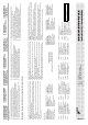
CE - DECLARACION-DE-CONFORMIDAD CE - DICHIARAZIONE-DI-CONFORMITA CE - ¢H§ø™H ™YMMOPºø™H™ 05 Nota * 04 Bemerk * 03 Remarque * 02 Hinweis * 01 Note * 19 ob upoštevanju določb: 20 vastavalt nõuetele: 21 следвайки клаузите на: 22 laikantis nuostatų, pateikiamų: 23 ievērojot prasības, kas noteiktas: 24 održiavajúc ustanovenia: 25 bunun koşullarına uygun olarak: delineato nel e giudicato positivamente da secondo il Certificato .
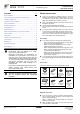
FMDQ50B7VEB FMDQ60B7VEB FMDQ71B7VEB CONTENTS FMDQ100B7VEB FMDQ125B7VEB Installation and operation manual Air conditioning system Page Before installation.............................................................................. 1 BEFORE ■ Leave the unit inside its packaging until you reach the installation site. Where unpacking is unavoidable, use a sling of soft material or protective plates together with a rope when lifting, this to avoid damage or scratches to the unit.
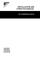
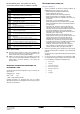
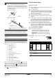
For the following items, take special care during construction and check after installation is finished SELECTING INSTALLATION SITE (See figure 1 and figure 2) Tick ✓ when checked ■ Is the indoor unit fixed firmly? The unit may drop, vibrate or make noise. ■ Is the gas leak test finished? It may result in insufficient cooling or heating. ■ Is the unit fully insulated and checked for air leaks? Condensate water may drip. ■ Does drainage flow smoothly? Condensate water may drip.
PREPARATIONS 1 BEFORE INSTALLATION Relation of ceiling opening to unit and suspension bolt position.
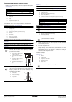
INDOOR ■ UNIT INSTALLATION When installing optional accessories (except for the air inlet panel), read also the installation manual of the optional accessories. Depending on the field conditions, it may be easier to install optional accessories before the indoor unit is installed. 1 2 Install the indoor unit temporarily. - Attach the hanger bracket to the suspension bolt. Be sure to fix it securely by using a nut and washer from the upper and lower sides of the hanger bracket.
Cautions for brazing - ■ - ■ Be sure to carry out a nitrogen blow when brazing. Brazing without carrying out nitrogen replacement or releasing nitrogen into the piping will create large quantities of oxidized film on the inside of the pipes, adversely affecting valves and compressors in the refrigerating system and preventing normal operation. ■ When brazing while inserting nitrogen into the piping, nitrogen must be set to 0.
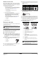
ELECTRIC Caution for drain socket WIRING WORK Do not remove the drain pipe plug. Water might leak out. The drain outlet is only used to discharge water if the drain pump is not used or before maintenance. Gently put in and out the drain plug. Excessive force may deform the drain socket of the drain pan. ■ Pulling out the plug General instructions ■ All field supplied parts and materials and electric works must conform to local codes. ■ Use copper wire only.
Specifications for field supplied fuses and wire - When connecting wires of the same gauge, connect them according to the figure. Power supply wiring Model Field fuses Wire Size 16 A H05VV-U3G Local codes 50~125 Model 50~125 Wire Size Sheathed wire (2) 0.75-1.25 mm2 Use the specified electric wire. Connect the wire securely to the terminal. Lock the wire down without applying excessive force to the terminal. Use torques according to the table below.
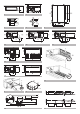
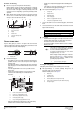
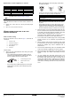
Fit the power supply wiring of each unit with a switch and fuse as shown in figure 16. 1 Power supply 2 Main switch 3 Power supply wiring 4 Transmission wiring 5 Switch 6 Fuse 7 Indoor unit 8 Remote controller FIELD SETTING Field setting must be made on the remote controller in function of the installation condition. ■ Setting can be made by changing the "Mode number", "First code No." and "Second code No.".
External static pressure settings ■ If there is no change after airflow adjustment in the ventilation paths, be sure to perform setting the automatic airflow adjustment again. ■ Contact your dealer if there is no change after performing airflow adjustment in the ventilation paths, after performing the test operation of the outdoor unit or when the air conditioning unit is moved to another location.
Computerised control (forced off and on/off operation) 1 Wire specifications and how to perform wiring - Connect input from outside to terminals T1 and T2 of the terminal board (remote controller to transmission wiring). TEST Refer to the installation manual of the outdoor unit. The operation lamp of the remote controller will flash when an error occurs. Check the error code on the liquid crystal display to identify the trouble. Wire specification Sheathed vinyl cord or cable (2 wire) Gauge 0.75-1.
If chains are present, unhook the chains. 5 Shut the air inlet grille. (Only for bottom suction.) Refer to item no. 1. 6 After turning on the power, press FILTER SIGN RESET button. The "TIME TO CLEAN AIR FILTER" display is turned off. How to clean air outlet and outside panels 2 Remove the air filters. ■ Clean with soft cloth. Remove the air filters by pulling their cloth upward (rear suction) or backward (bottom suction). ■ When it is difficult to remove stains, use water of neutral detergent.
WIRING DIAGRAM : FIELD WIRING : CONNECTOR : WIRE CLAMP : PROTECTIVE EARTH (SCREW) : LIVE : NEUTRAL L N BLK BLU BRN GRN GRY : BLACK : BLUE : BROWN : GREEN : GREY ORG PNK RED WHT YLW : ORANGE : PINK : RED : WHITE : YELLOW A1P........................ PRINTED CIRCUIT BOARD R3T ........................ THERMISTOR (GAS) A2P........................ PRINTED CIRCUIT BOARD (FAN) R5T ........................ THERMISTOR NTC (CURRENT LIMITING) A3P........................
NOTES
12 5 13 1 Control box IN/D OUT/D F1 F2 F1 F2 L N 4 1 3 2 L N 12 L N P1 P2 F1 F2 T1 T2 L N L N P1 P2 F1 F2 T1 T2 L N L N P1 P2 F1 F2 T1 T2 L N P1 P2 F1 F2 T1 T2 4 2 14 P1 P2 P1 P2 P1 P2 P1 P2 3 14 13 5 10 15 1 Control box IN/D OUT/D F1 F2 F1 F2 L N 13 L N L N P1 P2 F1 F2 T1 T2 L N P1 P2 F1 F2 T1 T2 L N P1 P2 F1 F2 T1 T2 L N P1 P2 F1 F2 T1 T2 4 2 11 6 9 8 6 7 12 P1 P2 P1 P2 3 14 5 15 16 1 3 5 4 6 17 2 18 1 2 2 S M 7 3 S 1 3 4 SETTING M 8 16 17
4PW48241-1 Copyright © Daikin