
Specifications


Example of connection (R-410A Type) SiBE28-805
246 Appendix
a
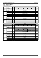
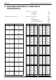
Pipe size selection
A,B,C. Piping between outdoor unit and refrigerant branc
h kit
• Choose from the following table in accordance with the outdoor unit total
capacity type, connected downstream.
Outdoor unit connection piping size
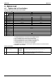
D. Piping between refrigerant branch kits
• Choose from the following table in accordance with the total capacity of
all the indoor units connected below this.
• Do not let the connection piping exceed the refrigerant piping size
chosen by general system model name.
E. Piping between refrigerant branch kit and indoor unit
• Pipe size for direct connection to indoor unit must be the same as the
connection size of indoor unit.
When the equivalent pipe length between outdoor and indoor units is 90 m or more
, the size of the main pipes (both gas side and liquid side) must be increased.
Depending on the length of the piping, the capacity ma
y drop, but even in such a case it is possible to increase the size of the main pipes.
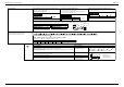
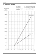
How to calculate the additional refrigerant to be charged
Additional refrigerant to be charged R (kg)
R should be rounded off in units of 0.1 kg
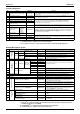
Note
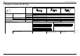
Allowable length after the first refrigerant branch kit to indoor units is 40 m or less, however it can be extended up to 90 m if all the following conditions are fulfilled.
Required conditions
Example drawings
It is necessary to increase the pipe size of the liquid and the gas pipe if the pipe length between the first
and the final branch kit is over 40 m (reducers must be procured on site).
If the increased pipe size is larger than the pipe size of the main pipe, then the pipe size of the main pipe
needs to be increased as well.
indoor unit 4: b+c+d≤90 m
increase the pipe size of b, c, d
Increase the pipe size as follows
* If available on the site. Otherwise it can not be increased.
For calculation of total extension length, the actual length of abo
ve pipes must be doubled (except main
pipe and the pipes that not increase the pipe size).
a+b*2+c*2+d*2≤200 m
Indoor unit to the nearest branch kit ≤40 m. e, f, g, h≤40 m
The difference between the distance of the outdoor unit to the farthest indoor unit and the distance of the
outdoor unit to the nearest indoor unit ≤40 m.
The farthest indoor unit 4
The nearest indoor unit 1
(a+b+c+d)–(a+e)≤40 m
Outdoor unit
capacity type
Piping size (outer diameter) (mm)
Gas pipe Liquid pipe
CMSQ200 15.9
9.5
CMSQ250 19.1
Indoor or outdoor unit
total capacity
Piping size (outer diameter) (mm)
Gas pipe Liquid pipe
<150 15.9
9.5
150≤x<200 19.1
200≤x<250 22.2
Indoor capacity type
Piping size (outer diameter) (mm)
Gas pipe Liquid pipe
50 12.7 6.4
60~125 15.9 9.5
Gas side Liquid side
CMSQ200 15.9 → 19.1 CMSQ200 9.5 —
CMSQ250 19.1 → 22.2 CMSQ250 9.5 → 12.7
— Increase is not allowed
Outdoor
unit
Indoor unit
Main
pipes
First refrigerant branch kit
Increase
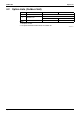
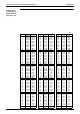
X1...6 = Total length (m) of liquid piping size at a
Example for refrigerant branch using refnet joint and refnet header f
or CMSQ250
If the outdoor unit is CMSQ250 and the piping lengths are as belo
w
9.5 → 12.7 15.9 → 19.1 22.2 → 25.4*
12.7 → 15.9 19.1 → 22.2
ab c d
H1
h
ABCD
123
4
H2
efg
1
2
3
1 Outdoor unit
2 Refnet joints (A~D)
3 Indoor units (1~4)