SiBE28 - 805 SkyAir CMSQ200A7W1B, 250A7W1B FMCQ50-125A7VEB FMDQ50-125A7V3B R-410A Heat Pump 50Hz
SiBE28-805 CMS R-410A Heat Pump 50Hz 1. Introduction ............................................................................................ vi 1.1 Safety Cautions ....................................................................................... vi 1.2 PREFACE ................................................................................................x Part 1 General Information ........................................................... 1 1. Model Names of Indoor/Outdoor Units.............
SiBE28-805 3.6 Stopping Operation ................................................................................45 4. Protection Control .................................................................................47 4.1 4.2 4.3 4.4 4.5 High Pressure Protection Control...........................................................47 Low Pressure Protection Control............................................................48 Discharge Pipe Protection Control ............................................
SiBE28-805 3.8 “C4” Indoor Unit: Malfunction of Thermistor (R2T) for Heat Exchanger....................................................................................147 3.9 “C5” Indoor Unit: Malfunction of Thermistor (R3T) for Gas Pipes .........148 3.10 “C9” Indoor Unit: Malfunction of Thermistor (R1T) for Suction Air.........149 3.11 “CC” Indoor Unit: Malfunction of Humidity Sensor System ....................150 3.12 “CJ” Indoor Unit: Malfunction of Thermostat Sensor in Remote Controller...............
SiBE28-805 3.46 “U9” Indoor Unit: Malfunction of Transmission Between Indoor and Outdoor Units in the Same System....................................202 3.47 “UA” Improper Combination of Indoor and Outdoor Units, Indoor Units and Remote Controller.....................................................203 3.48 “UC” Address Duplication of Centralized Controller...............................205 3.49 “UE” Malfunction of Transmission Between Centralized Controller and Indoor Unit ................................
SiBE28-805 Index ............................................................................................. i Drawings & Flow Charts ................................................................
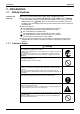
Introduction SiBE28-805 1. Introduction 1.1 Safety Cautions Cautions and Warnings Be sure to read the following safety cautions before conducting repair work. The caution items are classified into “ Warning” and “ Caution”. The “ Warning” items are especially important since they can lead to death or serious injury if they are not followed closely. The “ Caution” items can also lead to serious accidents under some conditions if they are not followed.
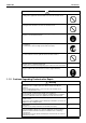
SiBE28-805 Introduction Caution Do not repair the electrical components with wet hands. Working on the equipment with wet hands can cause an electrical shock. Do not clean the air conditioner by splashing water. Washing the unit with water can cause an electrical shock. Be sure to provide the grounding when repairing the equipment in a humid or wet place, to avoid electrical shocks. Be sure to turn off the power switch and unplug the power cable when cleaning the equipment.
Introduction SiBE28-805 Warning Be sure to use the specified cable to connect between the indoor and outdoor units. Make the connections securely and route the cable properly so that there is no force pulling the cable at the connection terminals. Improper connections can cause excessive heat generation or fire. When connecting the cable between the indoor and outdoor units, make sure that the terminal cover does not lift off or dismount because of the cable.
SiBE28-805 Introduction Caution Check to see if the parts and wires are mounted and connected properly, and if the connections at the soldered or crimped terminals are secure. Improper installation and connections can cause excessive heat generation, fire or an electrical shock. If the installation platform or frame has corroded, replace it. Corroded installation platform or frame can cause the unit to fall, resulting in injury. Check the grounding, and repair it if the equipment is not properly grounded.
Introduction 1.2 SiBE28-805 PREFACE Thank you for your continued patronage of Daikin products. This is the new service manual for Daikin's Year 2008 CMSQ-A series Heat Pump System. Daikin offers a wide range of models to respond to building and office air conditioning needs. We are confident that customers will be able to find the models that best suit their needs. This service manual contains information regarding the servicing of CMSQ-A series R-410A Heat Pump System.
SiBE28-805 Part 1 General Information 1. Model Names of Indoor/Outdoor Units....................................................2 2. External Appearance...............................................................................3 2.1 Indoor Units ..............................................................................................3 2.2 Outdoor Units ...........................................................................................3 3. Combination ......................................
Model Names of Indoor/Outdoor Units SiBE28-805 1.
SiBE28-805 External Appearance 2. External Appearance 2.1 Indoor Units Ceiling Mounted Cassette Type (Round Flow) FMCQ50A FMCQ60A FMCQ71A FMCQ100A FMCQ125A 2.
Combination SiBE28-805 3. Combination Notes: 3.
SiBE28-805 Model Selection 4. Model Selection Connectable Indoor Unit Type Model Name Power Supply Ceiling Mounted Cassette Type (Multi Flow) FMCQ 50A 60A 71A 100A 125A VE Ceiling Mounted Built-In Type FMDQ 50A 60A 71A 100A 125A V3 Indoor unit capacity New refrigerant model code Selecting model capacity Equivalent output P50 type P60 type P71 type P100 type P125 type 5.0~5.6kW 6.0~7.0kW 7.1~8.0kW 10.0~11.2kW 12.5~14.0kW 2.0HP 2.3HP 2.
Model Selection 6 SiBE28-805 General Information
SiBE28-805 Part 2 Specifications 1. Specifications ..........................................................................................8 1.1 Outdoor Units ...........................................................................................8 1.2 Indoor Units ............................................................................................
Specifications SiBE28-805 1. Specifications 1.1 Outdoor Units CMSQ200, 250A7W1B Heat Pump 50Hz TECHNICAL SPECIFICATIONS Capacity COP CMSQ200A7W1B CMSQ250A7W1B Cooling kW 20.0 25.0 Heating kW 22.4 28.0 3.03 3.71 3.86 4.10 Cooling Heating Capacity Range Power Input (nominal)(50Hz) HP 8 10 Cooling kW 6.60 6.74 Heating kW 5.
SiBE28-805 Specifications TECHNICAL SPECIFICATIONS Cooling Sound level Night Quiet CMSQ200A7W1B CMSQ250A7W1B Sound Power (Nominal) dBA 78 81 Sound Pressure (Nominal) dBA 57 59 Level 1 / Level 2 / Level 3 dBA 55 / 50 / 45 Name Refrigerant R-410A Charge kg 6.2 Control Nr of Circuits Refrigerant Oil Piping connections 1 Name Synthetic (ether) Oil Charged Volume Liquid (OD) Gas 7.7 Expansion Valve (Electronic Type) l 1.7 Type Diameter (OD) mm 9.
Specifications SiBE28-805 ELECTRICAL SPECIFICATIONS CMSQ200A7W1B Name Power Supply Phase Voltage Range Hz 50 Voltage V 400 Cooling A 9.53 9.73 Heating A 8.38 9.86 Minimum Ssc Value kVa Minimum Circuit Amps (MCA) A 11.9 Maximum Fuse Amps (MFA) A 16 25 Total Overcurrent Amps (TOCA) A 15.6 16.5 Full Load Amps (FLA) A 0.
SiBE28-805 1.2 Specifications Indoor Units FMCQ50-125A7VEB FOR INDOOR UNITS ONLY Nominal Input (Indoor only) FMCQ50A7VEB FMCQ60A7VEB FMCQ71A7VEB FMCQ100A7VEB FMCQ125A7VEB Cooling kW 5.0 6.0 7.1 10.0 12.5 Heating kW 5.6 6.7 8.0 11.2 14.
Specifications SiBE28-805 TECHNICAL SPECIFICATIONS FMCQ50A7VEB FMCQ60A7VEB Item FMCQ71A7VEB FMCQ100A7VEB FMCQ125A7VEB 1 1 1 1 Operation Manual Quantity 1 1 1 Item Installation Manual Quantity 1 1 1 Drain Hose Clamp for Drain Hose Standard Accessories Washer for Hanging Bracket Screws Item Installation Guide Insulation for Fitting Sealing Pads Drain Sealing Pad The sound pressure values are mentioned for a unit installed with rear suction The sound power level is an absolute value
SiBE28-805 Specifications FMDQ50-125A7V3B FOR INDOOR UNITS ONLY FMDQ50A7V3B FMDQ60A7V3B FMDQ71A7V3B Nominal Input (Indoor only) Cooling kW 5.0 6.0 7.1 10.0 Heating kW 5.6 6.7 8.0 11.2 14.0 Nominal Total Input Power Cooling kW 0.143 0.189 0.234 0.242 0.321 Heating kW 0.123 0.169 0.214 0.222 0.
Specifications SiBE28-805 TECHNICAL SPECIFICATIONS FMDQ50A7V3B FMDQ60A7V3B Air Filter FMDQ71A7V3B FMDQ100A7V3B FMDQ125A7V3B Resin net with Mold Resistance Air Direction Control Up and Downwards Temperature Control Microprocessor Thermostat for Cooling and Heating PC Board Fuse Safety Devices Drain Pump Fuse Fan Motor Thermal Protector Nominal cooling capacities are based on : indoor temperature : 27°CDB, 19°CWB, outdoor temperature : 35°CDB, equivalent refrigerant piping : 8m, level difference
SiBE28-805 Part 3 Refrigerant Circuit 1. Refrigerant Circuit .................................................................................16 1.1 CMSQ200A7 ..........................................................................................16 1.2 CMSQ250A7 ..........................................................................................18 2. Functional Parts Layout ........................................................................20 2.1 CMSQ200A7 ...................................
Refrigerant Circuit SiBE28-805 1. Refrigerant Circuit 1.1 CMSQ200A7 No. in refrigerant Symbol system diagram Major Function A M1C Inverter compressor (INV) Inverter compressor is operated on frequencies between 52Hz and 188Hz by using the inverter. The number of operating steps is as follows when Inverter compressor is operated. CMSQ200A7 : 18 steps D M1F Inverter fan Since the system is of air heat exchanging type, the fan is operated at 9-step rotation speed by using the inverter.
SiBE28-805 Refrigerant Circuit CMSQ200A7 T 4 5 E D K 6 M N 1 P 3 J G W A 2 O 4TW31345-1 Refirgerant Circuit 17
Refrigerant Circuit 1.2 SiBE28-805 CMSQ250A7 No. in refrigerant Symbol system diagram 18 Name Major Function A M1C Inverter compressor (INV) Inverter compressor is operated on frequencies between 52Hz and 266Hz by using the inverter, while Standard compressor is operated with commercial power supply only. The number of operating steps is as follows when Inverter compressor is operated in combination with Standard compressor.
SiBE28-805 Refrigerant Circuit CMSQ250A7 4 E V F T D 5 7 M N G 1 6 P 3 J W A O 2 4TW31355-1 Refirgerant Circuit 19
Functional Parts Layout SiBE28-805 2. Functional Parts Layout 2.
SiBE28-805 2.
Refrigerant Flow for Each Operation Mode SiBE28-805 3.
SiBE28-805 Refrigerant Flow for Each Operation Mode Cooling Oil Return Operation Indoor unit operation Fan ON Fan OFF Fan ON " OFF " " ON " "High temperature, high pressure gas" "High temperature, high pressure liquid" "Low temperature, low pressure" Heat exchanger Heat exchanger Fan Fan Fan Filter EV:Nomal control Filter Electronic expansion valve Indoor unit Thermostat "ON" Refirgerant Circuit " ON " Heat exchanger Filter EV:224pls Filter Electronic expansion valve Indoor unit Filte
Refrigerant Flow for Each Operation Mode SiBE28-805 Heating Oil Return & Defrost Operation Indoor unit operation Fan OFF "High temperature, high pressure gas" "High temperature, high pressure liquid" "Low temperature, low pressure" " ON " Fan OFF Fan OFF " ON " Heat exchanger Heat exchanger Fan Fan Fan EV:416pls Filter EV:256pls Filter Filter EV:416pls Filter Electronic expansion valve Electronic expansion valve Indoor unit Indoor unit Thermostat "ON" 24 " OFF " Heat exchanger F
SiBE28-805 Refrigerant Flow for Each Operation Mode Heating Operation Indoor unit operation FanLL Fan ON " ON " "High temperature, high pressure gas" "High temperature, high pressure liquid" "Low temperature, low pressure" Fan OFF " ON " Heat exchanger Heat exchanger Heat exchanger Fan Fan Fan EV:Nomal control Filter EV:200pls Filter Electronic expansion valve Indoor unit Thermostat "ON" Refirgerant Circuit " OFF " Filter EV:200pls Filter Electronic expansion valve Indoor unit Filter F
Refrigerant Flow for Each Operation Mode SiBE28-805 CMSQ250A7 Cooling Operation Indoor unit operation Fan ON Fan ON " ON " "High temperature, high pressure gas" "High temperature, high pressure liquid" "Low temperature, low pressure" Fan OFF " OFF " " ON " Heat exchanger Heat exchanger Heat exchanger Fan Fan Fan Filter EV:Nomal control Filter Electronic expansion valve Indoor unit Filter EV:0pls Filter Electronic expansion valve Indoor unit Filter EV:0pls Filter Electronic expansion
SiBE28-805 Refrigerant Flow for Each Operation Mode Cooling Oil Return Operation Indoor unit operation Fan OFF Fan ON Fan ON " OFF " " ON " "High temperature, high pressure gas" "High temperature, high pressure liquid" "Low temperature, low pressure" " ON " Heat exchanger Heat exchanger Heat exchanger Fan Fan Fan Filter EV:Nomal control EV:224pls Filter Electronic expansion valve Indoor unit Thermostat "ON" Filter EV:Nomal Filter Electronic expansion valve Indoor unit Filter Filter El
Refrigerant Flow for Each Operation Mode SiBE28-805 Heating Oil Return & Defrost Operation Indoor unit operation "High temperature, high pressure gas" "High temperature, high pressure liquid" "Low temperature, low pressure" " ON " Fan OFF Heat exchanger " OFF " Fan OFF Heat exchanger " ON " Fan OFF Heat exchanger Fan Fan Fan EV:416pls Filter EV:256pls Filter Electronic expansion valve Indoor unit Thermostat "ON" Filter EV:416pls Filter Electronic expansion valve Indoor unit Filter Filter E
SiBE28-805 Refrigerant Flow for Each Operation Mode Heating Operation Indoor unit operation Fan ON Fan LL " ON " "High temperature, high pressure gas" "High temperature, high pressure liquid" "Low temperature, low pressure" Fan OFF " OFF " " ON " Heat exchanger Heat exchanger Heat exchanger Fan Fan Fan Filter EV:Nomal control EV:200pls Filter Electronic expansion valve Indoor unit Filter EV:200pls Filter Electronic expansion valve Indoor unit Thermostat "ON" Filter Filter Electronic
Refrigerant Flow for Each Operation Mode 30 SiBE28-805 Refirgerant Circuit
SiBE28-805 Part 4 Function 1. Function General...................................................................................32 1.1 Symbol ...................................................................................................32 1.2 Operation Mode......................................................................................33 2. Basic Control.........................................................................................34 2.1 2.2 2.3 2.4 2.5 Normal Operation ............
Function General SiBE28-805 1. Function General 1.
SiBE28-805 1.
Basic Control SiBE28-805 2. Basic Control 2.1 Normal Operation 2.1.
SiBE28-805 2.2 Basic Control Compressor PI Control Compressor PI Control Carries out the compressor capacity PI control to maintain Te at constant during cooling operation and Tc at constant during heating operation to ensure stable unit performance. [Cooling operation] Controls compressor capacity to adjust Te to achieve target value (TeS). Te set value (Make this setting while in Setting mode 2.
Basic Control SiBE28-805 Compressor Step Control Compressor operations vary with the following steps according to information in "2.2 Compressor PI Control". 50Hz Stand-alone installation CMSQ200 CMSQ250 No. 1 No. 1 INV INV STEP No. 1 2 3 4 5 6 7 8 9 10 11 12 13 14 15 16 17 18 INV 52 Hz 56 Hz 62 Hz 68 Hz 74 Hz 80 Hz 88 Hz 96 Hz 104 Hz 110 Hz 116 Hz 124 Hz 132 Hz 144 Hz 158 Hz 166 Hz 176 Hz 188 Hz STEP No.
SiBE28-805 2.3 Basic Control Electronic Expansion Valve PI Control Main Motorized Valve EV1 Control Carries out the motorized valve (Y1E) PI control to maintain the evaporator outlet superheated degree (SH) at constant during heating operation to make maximum use of the outdoor unit heat exchanger (evaporator).
Basic Control 2.5 SiBE28-805 Outdoor Unit Fan Control in Cooling Operation While in cooling operation, if the outdoor temperature is low, this mode provides high-pressure control using the outdoor unit fan to retain appropriate liquid pressure, thus ensuring refrigerant circulation rate to be supplied to indoor units. Upper limit of fan revolutions: Step 8 Pc<2.75MPa Pc>3.24MPa Upper limit of outdoor unit fan revolutions Step 7 *For fan revolutions in each step, refer to information on page 37.
SiBE28-805 Special Control 3. Special Control 3.1 Startup Control This control is used to equalize the pressure in the front and back of the compressor prior to the startup of the compressor, thus reducing startup loads. Furthermore, the inverter is turned ON to charge the capacitor. In addition, to avoid stresses to the compressor due to oil return or else after the startup, the following control is made and the position of the four way valve is also determined.
Special Control 3.2 SiBE28-805 Oil Return Operation In order to prevent the compressor from running out of oil, the oil return operation is conducted to recover oil flown out from the compressor to the system side. 3.2.1 Oil Return Operation in Cooling Operation [Start conditions] Referring to the set conditions for the following items, start the oil return operation in cooling.
SiBE28-805 Special Control 3.2.2 Oil Return Operation in Heating Operation Outdoor Unit Actuator Oil return preparation operation Oil return operation Post-oil-return operation Compressor Upper limit control 176 Hz 124 Hz 2-steps increase/20sec. till Pc - Pe>0.
Special Control 3.3 SiBE28-805 Defrosting Operation To defrost the outdoor unit heat exchanger while in Evaporator, the defrost operation is conducted to recover the heating capacity. [Start conditions] Referring to the set conditions for the following items, start the defrosting operation. • Heat transfer coefficient of the outdoor unit heat exchanger • Heat exchange temperature (Tb) • Timer (Set to two hours at minimum.
SiBE28-805 3.4 Special Control Pump-down Residual Operation 3.4.1 Pump-down Residual Operation in Cooling Operation If the liquid refrigerant stays in the Evaporator at the startup of a compressor, this liquid refrigerant enters the compressor, thus resulting in diluted oil in the compressor and then degraded lubrication performance. Consequently, in order to recover the refrigerant in the Evaporator while the compressor stops, the pump-down residual operation is conducted.
Special Control 3.5 SiBE28-805 Standby 3.5.1 Restart Standby Used to forcedly stop the compressor for a period of 3 minutes, in order to prevent the frequent ON/OFF of the compressor and equalize the pressure within the refrigerant system.
SiBE28-805 3.6 Special Control Stopping Operation 3.6.1 When System is in Stop Mode (Normal operation stop) This mode is used to define actuator operations when the system stops.
Special Control SiBE28-805 3.6.3 Stopping Operation of Slave Units During Master Unit is in Operation with Multi-Outdoor-Unit System While the master unit is in operation, this mode is used to set the refrigerant flow rate to a required level using a slave unit in the stopped mode. In cooling operation: Same as that of normal operation stop. In heating operation: The system operates with following mode.
SiBE28-805 Protection Control 4. Protection Control 4.1 High Pressure Protection Control This high pressure protection control is used to prevent the activation of protection devices due to abnormal increase of high pressure and to protect compressors against the transient increase of high pressure. [In cooling operation] ★ In the case of multi-outdoor-unit system, each outdoor unit performs this control individually in the following sequence.
Protection Control 4.2 SiBE28-805 Low Pressure Protection Control This low pressure protection control is used to protect compressors against the transient decrease of low pressure. [In cooling operation] ★ In the case of multi-outdoor-unit system, the entire system performs this control in the following sequence. Low pressure not limited Pe: LP pressure sensor detection value for master unit Pe>0.39MPa Pe<0.34MPa Low pressure limited Hot gas SVP = OFF Pe<0.25MPa Pe<0.15MPa Pe>0.
SiBE28-805 4.3 Protection Control Discharge Pipe Protection Control This discharge pipe protection control is used to protect the compressor internal temperature against a malfunction or transient increase of discharge pipe temperature. ★ Each compressor performs the discharge pipe temperature protection control individually in the following sequence.
Protection Control 4.4 SiBE28-805 Inverter Protection Control Inverter current protection control and inverter fin temperature control are performed to prevent tripping due to a malfunction, or transient inverter overcurrent, and fin temperature increase. ★ In the case of multi-outdoor-unit system, each INV compressor performs these controls in the following sequence. [Inverter overcurrent protection control] Nomal operation Invertercurrent >14.
SiBE28-805 4.5 Protection Control Injection Control (only for CMSQ200A7) For transitional rise in discharge pipe temperature, have the liquid refrigerant flow into the suction side to reduce the discharge pipe temperature for the compressor protection. SVT = OFF HTdi: Correction value of the discharge pipe HTdi>112˚C HTdi<107˚C temperature on the INV compressor.
Other Control SiBE28-805 5. Other Control 5.1 Demand Operation In order to save the power consumption, the capacity of outdoor unit is saved with control forcibly by using “Demand 1 Setting” or “Demand 2 Setting”. To operate the unit with this mode, additional setting of “Continuous Demand Setting” or external input by external control adaptor is required. Set item Demand 1 Demand 2 5.2 Condition Mode 1 Mode 2 Mode 3 Content The compressor operates at approx. 60% or less of rating.
SiBE28-805 Outline of Control (Indoor Unit) 6. Outline of Control (Indoor Unit) 6.1 Drain Pump Control 1. The drain pump is controlled by the ON/OFF buttons (4 button (1) - (4) given in the figure below). 6.1.1 When the Float Switch is Tripped while the Cooling Thermostat is ON: ∗ 1. The objective of residual operation is to completely drain any moisture adhering to the fin of the indoor unit heat exchanger when the thermostat goes off during cooling operation. 6.1.
Outline of Control (Indoor Unit) SiBE28-805 6.1.3 When the Float Switch is Tripped During Heating Operation: During heating operation, if the float switch is not reset even after the 5 minutes operation, 5 seconds stop, 5 minutes operation cycle ends, operation continues until the switch is reset. 6.1.4 When the Float Switch is Tripped and “AF” is Displayed on the Remote Controller: Note: 54 If the float switch is tripped five times in succession, a drain malfunction is determined to have occurred.
SiBE28-805 6.2 Outline of Control (Indoor Unit) Louver Control for Preventing Ceiling Dirt We have added a control feature that allows you to select the range of in which air direction can be adjusted in order to prevent the ceiling surrounding the air discharge outlet of ceiling mounted cassette type units from being soiled. (This feature is available on double flow, multiflow and corner types.
Outline of Control (Indoor Unit) 6.3 SiBE28-805 Thermostat Sensor in Remote Controller Temperature is controlled by both the thermostat sensor in remote controller and air suction thermostat in the indoor unit. (This is however limited to when the field setting for the thermostat sensor in remote controller is set to “Use”.
SiBE28-805 Heating Outline of Control (Indoor Unit) When heating, the hot air rises to the top of the room, resulting in the temperature being lower near the floor where the occupants are. When controlling by body thermostat sensor only, the unit may therefore be turned off by the thermostat before the lower part of the room reaches the preset temperature.
Outline of Control (Indoor Unit) 6.4 SiBE28-805 Thermostat Control while in Normal Operation The systems are set at factory to thermostat control mode using the remote controller. While in normal thermostat differential control mode (i.e., factory set mode), the thermostat turns OFF when the system reaches a temperature of -1°C from the set temperature while in cooling operation or of +1°C from that while in heating operation.
SiBE28-805 6.6 Outline of Control (Indoor Unit) Electronic Expansion Valve Control • Electronic expansion Valve Control In cooling, to maximize the capacity of indoor unit heat exchanger (evaporator), operate the electronic expansion valve under PI control so that the evaporator outlet superheated degree (SH) will become constant.
Outline of Control (Indoor Unit) 6.8 SiBE28-805 Freeze Prevention Freeze Prevention by Off Cycle (Indoor Unit) When the temperature detected by liquid pipe temperature thermistor (R2T) of the indoor unit heat exchanger drops too low, the unit enters freeze prevention operation in accordance with the following conditions, and is also set in accordance with the conditions given below. Conditions for starting freeze prevention: Temperature is -1°C or less for total of 40 min.
SiBE28-805 Outline of Control (Indoor Unit) (2) The heater control (ON/OFF) ON 50ºC is conducted by converting the heater temperature into the condensing pressure equivalent saturated temperature (Tc) according to the temperature detection through the high pressure sensor (SINPH) of the outdoor unit.
Outline of Control (Indoor Unit) 62 SiBE28-805 Function
SiBE28-805 Part 5 Test Operation 1. Test Operation ......................................................................................64 1.1 Installation Process ................................................................................64 1.2 Procedure and Outline ...........................................................................65 1.3 Operation when Power is Turned On .....................................................80 2. Outdoor Unit PC Board Layout ................................
Test Operation SiBE28-805 1. Test Operation 1.1 Installation Process Below figure shows the installation process. Install in the order of the steps shown. 3. Selection of Location 4. Inspecting and Handling the Unit 5. Placing the Unit 7. Field Wiring 6. Refrigerant Piping 8. Airtight Test and Vacuum Drying 9. Pipe Insulation 10. Checking of Device and Installation Conditions 11. Additional Refrigerant Charge and Check Operation Operations which require the power to be turned on. 13.
SiBE28-805 1.2 Test Operation Procedure and Outline Follow the following procedure to conduct the initial test operation after installation. 1.2.1 Check Work Prior to Turn Power Supply On Check the below items.
Test Operation SiBE28-805 1.2.2 Turn Power On Turn outdoor unit and indoor unit power on. Be sure to turn the power on 6 hours before starting operation to protect compressors. (to power on clankcase heater) Check the LED display of the outdoor unit PC board. Check to be sure the transmission is normal. The transmission is normal if the LEDs display conditions as shown in table below.
SiBE28-805 Test Operation 1.2.3 Leak Test and Vacuum Drying The units were checked for leaks by the manufacturer. After connecting the field piping, perform the following inspections. 1.2.3.1 Preparations Referring to figure 19, connect a nitrogen tank, a cooling tank, and a vacuum pump to the outdoor unit and perform the airtightness test and the vacuum drying.
Test Operation SiBE28-805 2. Following should be executed if there is a possibility of moisture remaining inside the pipe (if piping work is carried out during the raining season or over a long period of time, rainwater may enter the pipe during work). After evacuating the system for 2 hours, pressurize the system to 0.05 MPa (vacuum break) with nitrogen gas and evacuate the system again using the vacuum pump for 1 hour to –100.7 kPa (vacuum drying). If the system can not be evacuated to –100.
SiBE28-805 1.2.5.1 Test Operation Important Information Regarding the Refrigerant Used This product contains fluorinated greenhouse gases covered by the Kyoto Protocol. Do not vent gases into the atmosphere.
Test Operation 1.2.5.3 SiBE28-805 Stop Valve Operation Procedure Do not open the stop valve until all piping and electrical steps of "1.2.1. Check Work Prior to Turn Power Supply On" on page 65 are completed. If the stop valve is left open without turning on the power, it may cause refrigerant to build up in the compressor, leading to insulation degradation. Always use a charge hose for service port connection. After tightening the cap, check that no refrigerant leaks are present.
SiBE28-805 1.2.5.4 Test Operation How to Check How Many Units are Connected It is possible to find out how many indoor units are active and connected by operating the pushbutton switch on the printed circuit board (A1P) of the working outdoor unit. Make sure that all the indoor units connected to the outdoor unit are active. Follow the 5-step procedure as explained below. The LEDs on the A1P shows the operating status of the outdoor unit and the number of indoor units that are active.
Test Operation 1.2.5.5 SiBE28-805 Additional Refrigerant Charge Follow the procedures below. When charging a system, charging over the permissible quantity can cause liquid hammer. Always use protective gloves and protect your eyes when charging refrigerant. When the refrigerant charging procedure is done or when pausing, close the valve of the refrigerant tank immediately. If the tank is left with the valve open, the amount of refrigerant which is properly charged may get off point.
SiBE28-805 Test Operation Charging while the outdoor unit is operating 1. Completely open the gas line stop valve. Valve A must be left fully closed. Make sure the liquid stop valve is totally shut. If it is open, the refrigerant cannot be charged. Charge the additional refrigerant in its liquid state through the service port of the liquid line stop valve. 2.
Test Operation SiBE28-805 Pay attention to the fan. It is dangerous to inspect the unit while the fan is running. Be sure to turn off the main switch and to remove the fuses from the control circuit located in the outdoor unit. Note: Play it safe! For protection of the PC board, touch the switch box casing by hand in order to eliminate static electricity from your body before performing service. 1.2.6.
SiBE28-805 Test Operation Note: Make sure that all outside panels, except for the panel on the electric box, are closed while working. Close the lid of the electric box firmly before turning on the power. Location of the dip switches, LEDs and buttons LED H1~8P Push button switches BS1~BS5 DIP switch 1 (DS1: 1~4) DIP switch 2 (DS2: 1~4) DIP switch 3 (DS3: 1~2) Do not change the factory setting of the DIP switches.
Test Operation SiBE28-805 Setting the mode The set mode can be changed with the BS1 MODE button according to the following procedure: For setting mode 1: Press the BS1 MODE button once, the H1P LED is off h. For setting mode 2: Press the BS1 MODE button for 5 seconds, the H1P LED is on k. If the H1P LED is blinking l and the BS1 MODE button is pushed once, the setting mode will change to setting mode 1. Note: If you get confused in the middle of the setting process, push the BS1 MODE button.
SiBE28-805 Test Operation 3.2Possible settings for function D The noise of level 3 < level 2 < level 1 ( H1P k k k k H2P h h h h 1). H3P h h h h H4P h OFF (a) h 1 h 2 h 3 (a) This setting = factory setting H5P h h h h H6P h h l l H7P h l h l 3.3Possible settings for function E and F For function E (L.N.O.P) only: the noise of level 3 < level 2 < level 1 ( 1).
Test Operation SiBE28-805 In the check operation, the following checks and judgement will be performed: Check of the stop valve opening Check for wrong wiring Check of refrigerant overcharge Judgement of piping length It takes ±40 minutes to complete the check operation. Perform the test operation as described in the paragraph "Test operation procedure" on page 77. Test operation procedure 1. Close all front panels except the front panel of the electric box. 2.
SiBE28-805 Test Operation Correcting after abnormal completion of the test operation The test operation is only completed if there is no malfunction code displayed on the remote controller. In case of a displayed malfunction code, perform the following actions to correct the abnormality: Confirm the malfunction code on the remote controller Installation error The stop valve of an outdoor unit is left closed. Error code E3 E4 F3 UF Remedial action Check referring to the table in "1.2.5.
Test Operation 1.3 SiBE28-805 Operation when Power is Turned On 1.3.1 When Turning On Power First Time The unit cannot be run for up to 12 minutes to automatically set the master power and address (indoor-outdoor address, etc.). Status Outdoor unit Test lamp H2P .... Blinks Can also be set during operation described above. Indoor unit If ON button is pushed during operation described above, the "UH" malfunction indicator blinks. (Returns to normal when automatic setting is complete.) 1.3.
SiBE28-805 Outdoor Unit PC Board Layout 2.
Field Setting SiBE28-805 3. Field Setting 3.1 Field Setting from Remote Controller Individual function of indoor unit can be changed from the remote controller. At the time of installation or after service inspection / repair, make the local setting in accordance with the following description. Wrong setting may cause malfunction. (When optional accessory is mounted on the indoor unit, setting for the indoor unit may be required to change. Refer to information in the option handbook.) 3.1.
SiBE28-805 Field Setting 3.1.2 Wireless Remote Controller - Indoor Unit BRC7F type BRC4C type 1. When in the normal mode, push the “ ” button for 4 seconds or more, and operation then enters the “field set mode.” 2. Select the desired “mode No.” with the “ ” button. 3. Pushing the “ ” button, select the first code No. 4. Pushing the “ ” button, select the second code No. 5. Push the timer “ ” button and check the settings. 6. Push the “ ” button to return to the normal mode.
Field Setting SiBE28-805 3.1.3 Simplified Remote Controller BRC2A51 BRC2C51 1. Remove the upper part of remote controller. 2. When in the normal mode, press the [BS6] BUTTON ( ) (field set), and the FIELD SET MODE is entered. 3. Select the desired MODE No. with the [BS2] BUTTON ( ) (temperature setting ▲) and the [BS3] BUTTON ( ) (temperature setting ▼). 4. During group control, when setting by each indoor unit (mode No. 20, 22, and 23 have been selected), push the [BS8] ( ) BUTTON (unit No.
SiBE28-805 Field Setting 3.1.4 Setting Contents and Code No. – Indoor unit Mode Setting Switch No. Note 2 No. 0 10 (20) 1 2 3 4 5 6 9 0 1 13 (23) 4 6 1 2 15 (25) 3 5 Notes : Test Operation Long life filter Standard filter Thermostat sensor in remote controller Display time to clean air filter calculation (Set when filter sign is not to be displayed.) 0 04 Details No. — — (1) — — (2) Use Approx. 1,250 hrs. Approx. 100 hrs.
Field Setting SiBE28-805 3.1.5 Applicable Range of Field Setting Ceiling mounted cassette type Ceiling mounted built-in type Details No.
SiBE28-805 Field Setting 3.1.6 Detailed Explanation of Setting Modes (1) Filter Sign Setting If switching the filter sign ON time, set as given in the table below. Set Time Filter Specs. Setting Contamination Light Contamination Heavy Standard Long Life Ultra Long Life Filter 200 hrs. 100 hrs. 2,500 hrs. 1,250 hrs. 10,000 hrs. 5,000 hrs. (2) Ultra-Long-Life Filter Sign Setting When a Ultra-long-life filter is installed, the filter sign timer setting must be changed. Setting Table Mode No.
Field Setting SiBE28-805 (6) External ON/OFF Input This input is used for "ON / OFF operation" and "Protection device input" from the outside. The input is performed from the T1-T1 terminal of the operation terminal block (X1A) in the electric component box. F2 T1 T2 Forced stop Input A Setting Table Mode No. Setting Switch No. Setting Position No.
SiBE28-805 Field Setting (10) Auto Restart after Power Failure Reset For the air conditioners with no setting for the function (same as factory setting), the units will be left in the stop condition when the power supply is reset automatically after power failure reset or the main power supply is turned on again after once turned off.
Field Setting SiBE28-805 In the Case of FMCQ100~125 (*24-Way, 3-Way, 2-Way Outlets) Mode No. 13 (23) First Second Ceiling height code code Setting 4-way Outlets 3-way Outlets 2-way Outlets No. No. 01 Standard (N) Lower than 3.4 m Lower than 3.6 m Lower than 4.2 m 0 02 High Ceiling (H) Lower than 3.9 m Lower than 4.0 m Lower than 4.2 m 03 Higher Ceiling (S) Lower than 4.5 m Lower than 4.2 m — *1 “Mode No.” setting is done in a batch for the group.
SiBE28-805 Field Setting (17) Setting of Direct Duct Connection This is used when "fresh air intake kit equipped with fan" is connected. The indoor fan carries out residual operation for one minute after the thermostat is stopped. (For the purpose of preventing dust on the air filter from falling off.) Mode No. First Code No. Second Code No.
Field Setting SiBE28-805 3.1.7 Centralized Control Group No. Setting BRC1C Type In order to conduct the central remote control using the central remote controller and the unified ON/OFF controller, Group No. settings should be made by group using the operating remote controller. Make Group No. settings for central remote control using the operating remote controller. 1. Turn ON the power of the indoor unit and unified ON/OFF controller. (Unless the power is ON, no setting can be made.
SiBE28-805 Field Setting Group No. setting by wireless remote controller for centralized control 1. When in the normal mode, push “ ” button for 4 seconds or more, and operation then enters the “field set mode.” 2. Set mode No. “00” with “ ” button. 3. Set the group No. for each group with “ ”“ ” button (advance/backward). 4. Enter the selected group numbers by pushing “ ” button. 5. Push “ ” button and return to the normal mode. BRC7F Type BRC4C Type Group No.
Field Setting SiBE28-805 3.1.8 Setting of Operation Control Mode from Remote Controller (Local Setting) The operation control mode is compatible with a variety of controls and operations by limiting the functions of the operation remote controller. Furthermore, operations such as remote controller ON/OFF can be limited in accordance with the combination conditions. (Refer to information in the next page.) Central remote controller is normally available for operations.
SiBE28-805 How to Select Operation Mode Example ON by remote controller (Unified ON by central remote controller) ↓ Rejection Field Setting Whether operation by remote controller will be possible or not for turning on/off, controlling temperature or setting operation mode is selected and decided by the operation mode given on the right edge of the table below.
Field Setting 3.2 SiBE28-805 Field Setting from Outdoor Unit 3.2.1 Field Setting from Outdoor Unit List of Field Setting Items This following section indicates the list of field setting items. For the lists of dip switch contents, Setting mode 1, and Setting mode 2, refer to information in tables shown on the following page onward. For setting items of (*1), refer to detailed information provided on page 108 onward.
SiBE28-805 Field Setting Setting item Content and objective of setting Overview of setting procedure Indoor unit fan Set No. 5 of "Setting mode 2" to indoor unit Used to operate the indoor unit in the 1 forced H operation forced fan H. stopped state in forced H operation mode. 2 3 4 5 Service setting 6 7 8 9 10 11 12 13 Indoor unit forced Used to operate the indoor unit in forced operation mode.
Field Setting SiBE28-805 Setting by dip switches Using dip switches on the PC board enables field setting shown below. However, make no changes of factory settings except for DS1-1. Dip switch No. DS1-1 Setting item Description Setting ON to set cool / heat select by Cool/Heat selector Cool / Heat select Used equipped with outdoor unit. OFF (Factory set) DS1-2 ~DS1-4 ON OFF (Factory set) Not used Do not change the factory settings.
SiBE28-805 Field Setting “Detail of DS1-1~4, DS2-1~4 setting” (for Overseas general) Unit Test Operation Setting method ( represents the position of switches) Heat Pump CMSQ200A7 Set DS2-1 to ON. Heat Pump CMSQ250A7 Set DS2-1 and DS2-3 to ON.
Field Setting SiBE28-805 Setting by push button switches The following settings are made by pushbutton switches on PC board. LED display Single-outdoor-unit system MODE H1P TEST H2P h h COOL/HEAT select IND H3P MASTER H4P SLAVE H5P Low noise H6P Demand H7P Multi; H8P k h h h h h (Factory setting) BS1 BS2 BS3 BS4 BS5 MODE SET RETURN TEST RESET There are the following three setting modes.
SiBE28-805 Field Setting a. “Setting mode 1” This mode is used to set and check the following items. 1. Set items ············ In order to make COOL/HEAT selection in a batch of outdoor unit group, change the setting. • COOL/HEAT selection (IND) ·····················Used to select COOL or HEAT by individual outdoor unit (factory set). 2. Check items ······· The following items can be checked.
Field Setting b. “Setting mode 2” Push and hold the MODE (BS1) button for 5 seconds and set to “Setting mode 2”. Push the SET (BS2) button and set the LED display to a setting item shown in the table on the right. ↓ Push the RETURN (BS3) button and decide the item. (The present setting condition is blinked.) SiBE28-805 No. Digital pressure gauge kit display 1 Sets address for cool/heat unified operation.
SiBE28-805 Field Setting No. 35 Test Operation Setting item Description Setting of difference Make the setting when the outdoor unit is installed 40 m in elevation for the or more below the indoor unit.
Field Setting SiBE28-805 Setting item display No.
SiBE28-805 Field Setting Setting item display No.
Field Setting c. Monitor mode To enter the monitor mode, push the MODE (BS1) button when in “Setting mode 1”. SiBE28-805 No. Setting item Push the RETURN (BS3) button to display different data of set items. Push the RETURN (BS3) button and switches to the initial status of “Monitor mode”. ∗ Push the MODE (BS1) button and returns to “Setting mode 1”.
SiBE28-805 Field Setting Setting item 0 Display contents of “Number of units for various settings” EMG operation / backup operation setting ON OFF Defrost select setting Short Medium Long Te setting L M H ~ Tc setting L M H l l l l l l l l l l l h h h h h h h h h h h h h h h h h h h h h h k h h h h h h h h h h h h k l h h h h h h h h h h h h h l k h h h h h h h h h h h h l k ★ Data such as addresses and number of units is expressed as binary numbers; the two ways of expressing are as foll
Field Setting SiBE28-805 3.2.2 Cool / Heat Mode Switching There are the following 4 cool/heat switching modes. c Set cool/heat separately for each outdoor unit system by indoor unit remote controller. d Set cool/heat separately for each outdoor unit system by cool/heat selector. e Set cool/heat for more than one outdoor unit system simultaneously in accordance with unified master outdoor unit by indoor unit remote controller.
SiBE28-805 Field Setting d Set Cool / Heat Separately for Each Outdoor Unit System by Cool / Heat Selector It does not matter whether or not there is outdoor - outdoor unit wiring. Set outdoor unit PC board DS1-1 to OUT (factory set). Set cool/heat switching to IND (individual) for “Setting mode 1” (factory set).
Field Setting SiBE28-805 3.2.3 Setting of Low Noise Operation and Demand Operation Setting of Low Noise Operation By connecting the external contact input to the low noise input of the outdoor unit external control adaptor (optional), you can lower operating noise by 2-3 dB. Setting Mode 1 Mode 2 Mode 3 Content Set the outdoor unit fan to Step 6 or lower. Set the outdoor unit fan to Step 5 or lower. Set the outdoor unit fan to Step 4 or lower. A.
SiBE28-805 Field Setting Image of operation in the case of A Image of operation in the case of B Image of operation in the case of A and B Test Operation 111
Field Setting SiBE28-805 Setting of Demand Operation By connecting the external contact input to the demand input of the outdoor unit external control adaptor (optional), the power consumption of unit operation can be saved suppressing the compressor operating condition. Set item Demand 1 Demand 2 Condition Mode 1 Mode 2 Mode 3 Content The compressor operates at approx. 60% or less of rating. The compressor operates at approx. 70% or less of rating. The compressor operates at approx.
SiBE28-805 Field Setting Image of operation in the case of A Power consumption Rated power consumption 80 % of rated power consumption 70 % of rated power consumption 60 % of rated power consumption Demand level 1 instructing Demand level 2 instructing Demand level 3 instructing Power consumption set by "Demand 1 level setting".
Field Setting SiBE28-805 Detailed Setting Procedure of Low Noise Operation and Demand Control 1. Setting mode 1 (H1P off) c In setting mode 2, push the BS1 (MODE button) one time. → Setting mode 1 is entered and H1P lights off. During the setting mode 1 is displayed, “In low noise operation” and “In demand control” are displayed. 2. Setting mode 2 (H1P on) c In setting 1, push and hold the BS1 (MODE button) for more than 5 seconds. → Setting mode 2 is entered and H1P lights.
SiBE28-805 Field Setting {: ON d c Setting No. Setting contents 22 External low noise / Demand setting { z z z z Setting No.
Field Setting SiBE28-805 3.2.4 Setting of Refrigerant Recovery Mode When carrying out the refrigerant collection on site, fully open the respective expansion valve of indoor and outdoor units. All indoor and outdoor unit’s operation are prohibited. [Operation procedure] c In setting mode 2 with units in stop mode, set “Refrigerant Recovery / Vacuuming mode” to ON. The respective expansion valve of indoor and outdoor units are fully opened.
SiBE28-805 Field Setting 3.2.5 Setting of Vacuuming Mode In order to perform vacuuming operation at site, fully open the expansion valves of indoor and outdoor units and turn on some solenoid valves. [Operating procedure] c With Setting Mode 2 while the unit stops, set “Refrigerant recovery / Vacuuming mode” to ON. The expansion valves of indoor and outdoor units fully open and some of solenoid valves open.
Field Setting 118 SiBE28-805 Test Operation
SiBE28-805 Part 6 Troubleshooting 1. Symptom-based Troubleshooting .......................................................121 2. Troubleshooting by Remote Controller ...............................................124 2.1 2.2 2.3 2.4 2.5 The INSPECTION / TEST Button.........................................................124 Self-diagnosis by Wired Remote Controller .........................................125 Self-diagnosis by Wireless Remote Controller .....................................
SiBE28-805 3.30 “L4” Outdoor Unit: Malfunction of Inverter Radiating Fin Temperature Rise .............................................175 3.31 “L5” Outdoor Unit: Inverter Compressor Abnormal ...............................177 3.32 “L8” Outdoor Unit: Inverter Current Abnormal.......................................179 3.33 “L9” Outdoor Unit: Inverter Start Up Error.............................................181 3.34 “LC” Outdoor Unit: Malfunction of Transmission Between Inverter and Control PC Board ......
SiBE28-805 Symptom-based Troubleshooting 1. Symptom-based Troubleshooting 1 Symptom The system does not start operation at all. Supposed Cause Blowout of fuse(s) Cutout of breaker(s) Countermeasure Turn Off the power supply and then replace the fuse(s). • If the knob of any breaker is in its OFF position, turn ON the power supply. • If the knob of any circuit breaker is in its tripped position, do not turn ON the power supply.
Symptom-based Troubleshooting 7 8 Symptom The system This symptom occurs conducts fan immediately after turning ON operation but not the power supply. cooling or heating operation. The airflow rate Even pressing the AIRFLOW is not RATE SET button makes no reproduced changes in the airflow rate. according to the setting. 9 The airflow direction is not reproduced according to the setting. 10 A white mist comes out from the system. 11 The system produces sounds.
SiBE28-805 Symptom-based Troubleshooting Symptom 12 Dust comes out Dust comes out from the from the system. system when it restarts after the stop for an extended period of time. 13 Odors come out In operation from the system. 14 Outdoor unit fan does not rotate. In operation 15 LCD display "88" appears on the remote controller. 16 The outdoor unit compressor or the outdoor unit fan does not stop. 17 The outdoor gets hot.
Troubleshooting by Remote Controller SiBE28-805 2. Troubleshooting by Remote Controller 2.1 The INSPECTION / TEST Button The following modes can be selected by using the [Inspection/Test Operation] button on the remote control. Indoor unit settings can be made • Filter sign time • Airflow direction • Others Depress Inspection/Test Operation button for more than 4 seconds. Local setting mode Service mode Depress Inspection/Test Operation button for more than 4 seconds. Service data can be obtained.
SiBE28-805 2.2 Troubleshooting by Remote Controller Self-diagnosis by Wired Remote Controller Explanation If operation stops due to malfunction, the remote controller’s operation LED blinks, and malfunction code is displayed. (Even if stop operation is carried out, malfunction contents are displayed when the inspection mode is entered.) The malfunction code enables you to tell what kind of malfunction caused operation to stop. See page 132 for malfunction code and malfunction contents.
Troubleshooting by Remote Controller 2.3 SiBE28-805 Self-diagnosis by Wireless Remote Controller In the Case of BRC7F Type BRC4C Type If equipment stops due to a malfunction, the operation indicating LED on the light reception section flashes. The malfunction code can be determined by following the procedure described below. (The malfunction code is displayed when an operation error has occurred. In normal condition, the malfunction code of the last problem is displayed.) 1.
SiBE28-805 Troubleshooting by Remote Controller The lower digit of the code changes as shown below when the UP and DOWN buttons are pressed.
Troubleshooting by Remote Controller 128 SiBE28-805 Troubleshooting
SiBE28-805 2.4 Troubleshooting by Remote Controller Remote Controller Service Mode How to Enter the Service Mode Service Mode Operation Method Troubleshooting 1. Select the mode No. Set the desired mode No. with the button. (For wireless remote controller, Mode 43 only can be set.) 2. Select the unit No. (For group control only) Select the indoor unit No. to be set with the time mode . (For wireless remote controller, button.) 3. Make the settings required for each mode.
Troubleshooting by Remote Controller Mode No 40 Function Malfunction hysteresis display Contents and operation method Display malfunction hysteresis. The history No. can be changed with the button. SiBE28-805 Remote controller display example Unit 1 Malfunction code 2-U4 40 Malfunction code Hystory No: 1 - 9 1: Latest 41 Display of sensor and address data Display various types of data. Select the data to be displayed with the button. Sensor data 0: Thermostat sensor in remote controller.
SiBE28-805 2.5 Troubleshooting by Remote Controller Remote Controller Self-Diagnosis Function The remote controller switches are equipped with a self diagnosis function so that more appropriate maintenance can be carried out. If a malfunction occurs during operation, the operation lamp, malfunction code and display of malfunctioning unit No. let you know the contents and location of the malfunction.
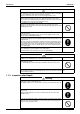
Troubleshooting by Remote Controller SiBE28-805 k : ON h : OFF Malfunction Operation Malfunction contents code lamp Indoor Unit A0 l Error of external protection device A1 l PC board defect A3 l Malfunction of drain level control system (S1L) A6 l Fan motor (M1F) lock, overload A9 l Malfunction of moving part of electronic expansion valve (Y1E) AF k Drain level above limit AH k Malfunction of air filter maintenance AJ l Malfunction of capacity Determination Device C4 l Malfunction of thermistor (R2T) for
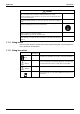
SiBE28-805 Troubleshooting by Remote Controller k : ON System Central Remote Controller and Schedule Timer Heat Reclaim Ventilation h : OFF l : Blink Malfunction Operation Malfunction contents Page code lamp Referred U0 k Low pressure drop due to refrigerant shortage or electronic expansion valve 190 failure U1 l Reverse phase, open phase 191 U2 l Power supply insufficient or instantaneous failure 192 U3 l Check operation not executed 195 U4 l Malfunction of transmission between indoor units 196 U5 l
Troubleshooting by Remote Controller SiBE28-805 Malfunction code indication by outdoor unit PC board Contents of malfunction To enter the monitor mode, push the MODE (BS1) button when in “Setting mode 1”. PC board malfunction Malfunction code PC board malfunction E1 Faulty PC board * Refer to P.106 for Monitor mode.
SiBE28-805 Troubleshooting by Remote Controller k : ON h : OFF l :Blink Confirmation of malfunction 1 Confirmation of malfunction 2 Confirmation of malfunction 3 Confirmation of malfunction 4 Malfunction code H1P H2P H3P H4P H5P H6P H7P H1P H2P H3P H4P H5P H6P H7P H1P H2P H3P H4P H5P H6P H7P H1P H2P H3P H4P H5P H6P H7P E6 l l l l l l h h h h h h h h h l l l h h l h h l l l l h l h E7 l h l l l E9 l l h h l l h l l l l l h h l l l l h h h h l h l l l l h h J3 l h h
Troubleshooting by Remote Controller SiBE28-805 Contents of malfunction To enter the monitor mode, push the MODE (BS1) button when in “Setting mode 1”. * Refer to P.106 for Monitor mode.
SiBE28-805 Troubleshooting by Remote Controller k : ON h : OFF l :Blink Confirmation of malfunction 1 Confirmation of malfunction 2 Confirmation of malfunction 3 Confirmation of malfunction 4 Malfunction code H1P H2P H3P H4P H5P H6P H7P H1P H2P H3P H4P H5P H6P H7P H1P H2P H3P H4P H5P H6P H7P H1P H2P H3P H4P H5P H6P H7P P1 l l h h h l h h h l l h h h h l h h P3 l h h l l l h h h h l h h P4 l h l h h l h h h h l h h PJ l l l h l h h h h h h h h l h l h h h h h h h h
Troubleshooting by Indication on the Remote Controller SiBE28-805 3. Troubleshooting by Indication on the Remote Controller 3.1 “A0” Indoor Unit: Error of External Protection Device Remote Controller Display A0 Applicable Models All indoor unit models Method of Malfunction Detection Detect open or short circuit between external input terminals in indoor unit.
SiBE28-805 3.2 Troubleshooting by Indication on the Remote Controller “A1” Indoor Unit: PC Board Defect Remote Controller Display A1 Applicable Models All indoor unit models Method of Malfunction Detection Check data from E²PROM. Malfunction Decision Conditions When data could not be correctly received from the E²PROM E²PROM : Type of nonvolatile memory. Maintains memory contents even when the power supply is turned off.
Troubleshooting by Indication on the Remote Controller 3.3 “A3” Indoor Unit: Malfunction of Drain Level Control System (S1L) Remote Controller Display A3 Applicable Models FMCQ, FMDQ Method of Malfunction Detection By float switch OFF detection Malfunction Decision Conditions When rise of water level is not a condition and the float switch goes OFF.
SiBE28-805 Troubleshooting by Indication on the Remote Controller Troubleshooting Caution Be sure to turn off power switch before connect or disconnect connector, or parts damage may be occurred. Is power supply 220~240V provided? NO Provide 220~240V power supply. YES The float switch is connected to X8A or X15A of the indoor unit PC board.
Troubleshooting by Indication on the Remote Controller 3.
SiBE28-805 3.5 Troubleshooting by Indication on the Remote Controller “A9” Indoor Unit: Malfunction of Moving Part of Electronic Expansion Valve (Y1E) Remote Controller Display A9 Applicable Models All indoor unit models Method of Malfunction Detection Use a microcomputer to check the electronic expansion valve for coil conditions. Malfunction Decision Conditions When the pin input of the electronic expansion valve is not normal while in the initialization of the microcomputer.
Troubleshooting by Indication on the Remote Controller SiBE28-805 ∗1: Coil check method for the moving part of the electronic expansion valve Disconnect the electronic expansion valve from the PC board and check the continuity between the connector pins. (Normal) Pin No. 1. White 2. Yellow 3. Orange 4. Blue 5. Red 1. White 2. Yellow × 3. Orange { Approx. 300Ω × 4. Blue × { Approx. 300Ω × 5. Red { Approx. 150Ω × { Approx. 150Ω × 6. Brown × { Approx. 150Ω × { Approx. 150Ω × 6.
SiBE28-805 3.6 Troubleshooting by Indication on the Remote Controller “AF” Indoor Unit: Drain Level above Limit Remote Controller Display AF Applicable Models FMCQ, FMDQ Method of Malfunction Detection Water leakage is detected based on float switch ON/OFF operation while the compressor is in non-operation. Malfunction Decision Conditions When the float switch changes from ON to OFF while the compressor is in non-operation.
Troubleshooting by Indication on the Remote Controller 3.7 SiBE28-805 “AJ” Indoor Unit: Malfunction of Capacity Determination Device Remote Controller Display AJ Applicable Models All indoor unit models Method of Malfunction Detection Capacity is determined according to resistance of the capacity setting adaptor and the memory inside the IC memory on the indoor unit PC board, and whether the value is normal or abnormal is determined.
SiBE28-805 3.8 Troubleshooting by Indication on the Remote Controller “C4” Indoor Unit: Malfunction of Thermistor (R2T) for Heat Exchanger Remote Controller Display C4 Applicable Models All indoor unit models Method of Malfunction Detection Malfunction detection is carried out by temperature detected by heat exchanger thermistor. Malfunction Decision Conditions When the heat exchanger thermistor becomes disconnected or shorted while the unit is running.
Troubleshooting by Indication on the Remote Controller 3.9 SiBE28-805 “C5” Indoor Unit: Malfunction of Thermistor (R3T) for Gas Pipes Remote Controller Display C5 Applicable Models All indoor unit models Method of Malfunction Detection Malfunction detection is carried out by temperature detected by gas pipe thermistor. Malfunction Decision Conditions When the gas pipe thermistor becomes disconnected or shorted while the unit is running.
SiBE28-805 Troubleshooting by Indication on the Remote Controller 3.10 “C9” Indoor Unit: Malfunction of Thermistor (R1T) for Suction Air Remote Controller Display C9 Applicable Models AII indoor unit models Method of Malfunction Detection Malfunction detection is carried out by temperature detected by suction air temperature thermistor. Malfunction Decision Conditions When the suction air temperature thermistor becomes disconnected or shorted while the unit is running.
Troubleshooting by Indication on the Remote Controller SiBE28-805 3.11 “CC” Indoor Unit: Malfunction of Humidity Sensor System Remote Controller Display CC Applicable Models FMCQ Method of Malfunction Detection Even if a malfunction occurs, operation still continues. Malfunction is detected according to the moisture (output voltage) detected by the moisture sensor.
SiBE28-805 Troubleshooting by Indication on the Remote Controller 3.12 “CJ” Indoor Unit: Malfunction of Thermostat Sensor in Remote Controller CJ Remote Controller Display Applicable Models AII indoor unit models Method of Malfunction Detection Malfunction detection is carried out by temperature detected by remote controller air temperature thermistor.
Troubleshooting by Indication on the Remote Controller SiBE28-805 3.13 “E1” Outdoor Unit: PC Board Defect Remote Controller Display E1 Applicable Models CMSQ200A7, 250A7 Method of Malfunction Detection Check data from E²PROM Malfunction Decision Conditions When data could not be correctly received from the E²PROM E²PROM : Type of nonvolatile memory. Maintains memory contents even when the power supply is turned off.
SiBE28-805 Troubleshooting by Indication on the Remote Controller 3.14 “E3” Outdoor Unit: Actuation of High Pressure Switch Remote Controller Display E3 Applicable Models CMSQ200A7, 250A7 Method of Malfunction Detection Abnormality is detected when the contact of the high pressure protection switch opens. Malfunction Decision Conditions Error is generated when the HPS activation count reaches the number specific to the operation mode.
Troubleshooting by Indication on the Remote Controller SiBE28-805 Troubleshooting Caution Be sure to turn off power switch before connect or disconnect connector, or parts damage may be occurred. Check for the points shown below. Is the stop valve open? Is the HPS connector properly connected to the main PC board? Does the high pressure switch have continuity? Are the three points above OK? NO Rectify defective points, if any. YES · Mount a pressure gauge on the high-pressure service port.
SiBE28-805 Troubleshooting by Indication on the Remote Controller 3.15 “E4” Outdoor Unit: Actuation of Low Pressure Sensor Remote Controller Display E4 Applicable Models CMSQ200A7, 250A7 Method of Malfunction Detection Abnormality is detected by the pressure value with the low pressure sensor. Malfunction Decision Conditions Error is generated when the low pressure is dropped under specific pressure. Operating pressure:0.
Troubleshooting by Indication on the Remote Controller SiBE28-805 Troubleshooting Caution Be sure to turn off power switch before connect or disconnect connector, or parts damage may be occurred. NO Is the stop valve open? Open the stop valve. YES Mount a pressure gauge on the low-pressure service port. Connect the Service Checker. Reset the operation using the remote controller, and then restart the operation. Are the characteristics of the low pressure sensor normal? (See *1.
SiBE28-805 Troubleshooting by Indication on the Remote Controller 3.16 “E5” Outdoor Unit: Inverter Compressor Motor Lock Remote Controller Display E5 Applicable Models CMSQ200A7, 250A7 Method of Malfunction Detection Inverter PC board takes the position signal from UVW line connected between the inverter and compressor, and the malfunction is detected when any abnormality is observed in the phasecurrent waveform.
Troubleshooting by Indication on the Remote Controller SiBE28-805 Troubleshooting Caution Be sure to turn off power switch before connect or disconnect connector, or parts damage may be occurred. Is the stop valve open? Power OFF NO On-site causes. Open the stop valve. YES Check the compressor cable for disconnection and flaws. The compressor cable has a defect. YES Repalce the cable, and then securely connect the connectors.
SiBE28-805 Troubleshooting by Indication on the Remote Controller 3.17 “E7” Outdoor Unit: Malfunction of Outdoor Unit Fan Motor Remote Controller Display E7 Applicable Models CMSQ200A7, 250A7 Method of Malfunction Detection Malfunction of fan motor system is detected according to the fan speed detected by hall IC when the fan motor runs.
Troubleshooting by Indication on the Remote Controller SiBE28-805 Troubleshooting Caution Be sure to turn off power switch before connect or disconnect connector, or parts damage may be occurred. Turn OFF the power supply, and then wait for a period of 10 minutes. Are there any foreign matters around the fan? YES Remove the foreign matters. NO Any of the fan motor connectors X1A or the relay harness connectors Z5C and X1A is disconnected. YES Insert the connector disconnected.
SiBE28-805 Troubleshooting by Indication on the Remote Controller Troubleshooting A CHECK 1 Check for the fan motor connector (Power supply cable) Resistance of the U, V, and W phases of the fan motor has got imbalanced or short circuits have been established amoung the U, V, and W phases. YES Replace the outdoor unit fan motor.
Troubleshooting by Indication on the Remote Controller SiBE28-805 3.18 “E9” Outdoor Unit: Malfunction of Moving Part of Electronic Expansion Valve (Y1E, Y2E) Remote Controller Display E9 Applicable Models CMSQ200A7, 250A7 Method of Malfunction Detection Check disconnection of connector Check continuity of expansion valve coil Malfunction Decision Conditions Error is generated under no common power supply when the power is on.
SiBE28-805 Troubleshooting by Indication on the Remote Controller Troubleshooting Caution Be sure to turn off power switch before connect or disconnect connector, or parts damage may be occurred. Turn power supply off, and turn power supply on again. Return to normal? YES NO Electronic expansion valve is connected to X21A and X23A of outdoor unit PC board (A1P). NO External factor other than malfunction (for example, noise etc.). After connecting, turn the power off and then back on again.
Troubleshooting by Indication on the Remote Controller SiBE28-805 3.19 “F3” Outdoor Unit: Abnormal Discharge Pipe Temperature Remote Controller Display F3 Applicable Models CMSQ200A7, 250A7 Method of Malfunction Detection Abnormality is detected according to the temperature detected by the discharge pipe temperature sensor.
SiBE28-805 Troubleshooting by Indication on the Remote Controller 3.20 “F6” Outdoor Unit: Refrigerant Overcharged Remote Controller Display F6 Applicable Models CMSQ200A7, 250A7 Method of Malfunction Detection Excessive charging of refrigerant is detected by using the outside air temperature, heat exchanging deicer temperature and liquid pipe temperature during a check run.
Troubleshooting by Indication on the Remote Controller SiBE28-805 3.21 “H7” Outdoor Unit: Abnormal Outdoor Fan Motor Signal Remote Controller Display H7 Applicable Models CMSQ200A7, 250A7 Method of Malfunction Detection Detection of abnormal signal from fan motor. Malfunction Decision Conditions In case of detection of abnormal signal at starting fan motor.
SiBE28-805 Troubleshooting by Indication on the Remote Controller 3.22 “H9” Outdoor Unit: Malfunction of Thermistor (R1T) for Outdoor Air Remote Controller Display H9 Applicable Models CMSQ200A7, 250A7 Method of Malfunction Detection Malfunction is detected from the temperature detected by the outdoor air thermistor. Malfunction Decision Conditions When the outside air temperature thermistor has short circuit or open circuit.
Troubleshooting by Indication on the Remote Controller SiBE28-805 3.23 “J3” Outdoor Unit: Malfunction of Discharge Pipe Thermistor (R3T) Remote Controller Display J3 Applicable Models CMSQ200A7, 250A7 Method of Malfunction Detection Malfunction is detected from the temperature detected by discharge pipe temperature thermistor. Malfunction Decision Conditions When a short circuit or an open circuit in the discharge pipe temperature thermistor is detected.
SiBE28-805 Troubleshooting by Indication on the Remote Controller 3.24 “J5” Outdoor Unit: Malfunction of Thermistor (R2T, R7T) for Suction Pipe Remote Controller Display J5 Applicable Models CMSQ200A7, 250A7 Method of Malfunction Detection Malfunction is detected from the temperature detected by the suction pipe temperature thermistor. Malfunction Decision Conditions When a short circuit or an open circuit in the suction pipe temperature thermistor is detected.
Troubleshooting by Indication on the Remote Controller SiBE28-805 3.25 “J6” Outdoor Unit: Malfunction of Thermistor (R4T) for Outdoor Unit Heat Exchanger Remote Controller Display J6 Applicable Models CMSQ200A7, 250A7 Method of Malfunction Detection Malfunction is detected from the temperature detected by the heat exchanger thermistor. Malfunction Decision Conditions When a short circuit or an open circuit in the heat exchange thermistor is detected.
SiBE28-805 Troubleshooting by Indication on the Remote Controller 3.26 “J7” Outdoor Unit: Malfunction of Liquid Pipe Thermistor (R6T) Remote Controller Display J7 Applicable Models CMSQ200A7, 250A7 Method of Malfunction Detection Malfunction is detected according to the temperature detected by liquid pipe thermistor. Malfunction Decision Conditions When the liquid pipe thermistor is short circuited or open.
Troubleshooting by Indication on the Remote Controller SiBE28-805 3.27 “J9” Outdoor Unit: Malfunction of Subcooling Heat Exchanger Gas Pipe Thermistor (R5T) Remote Controller Display J9 Applicable Models CMSQ200A7, 250A7 Method of Malfunction Detection Malfunction is detected according to the temperature detected by subcooling heat exchanger gas pipe thermistor. Malfunction Decision Conditions When the subcooling heat exchanger gas pipe thermistor is short circuited or open.
SiBE28-805 Troubleshooting by Indication on the Remote Controller 3.28 “JA” Outdoor Unit: Malfunction of High Pressure Sensor Remote Controller Display JA Applicable Models CMSQ200A7, 250A7 Method of Malfunction Detection Malfunction is detected from the pressure detected by the high pressure sensor. Malfunction Decision Conditions When the high pressure sensor is short circuit or open circuit.
Troubleshooting by Indication on the Remote Controller SiBE28-805 3.29 “JC” Outdoor Unit: Malfunction of Low Pressure Sensor Remote Controller Display JC Applicable Models CMSQ200A7, 250A7 Method of Malfunction Detection Malfunction is detected from pressure detected by low pressure sensor. Malfunction Decision Conditions When the low pressure sensor is short circuit or open circuit. Supposed Causes Defect of low pressure sensor system Connection of high pressure sensor with wrong connection.
SiBE28-805 Troubleshooting by Indication on the Remote Controller 3.30 “L4” Outdoor Unit: Malfunction of Inverter Radiating Fin Temperature Rise Remote Controller Display L4 Applicable Models CMSQ200A7, 250A7 Method of Malfunction Detection Fin temperature is detected by the thermistor of the radiation fin. Malfunction Decision Conditions When the temperature of the inverter radiation fin increases above 93°C.
Troubleshooting by Indication on the Remote Controller SiBE28-805 Inverter PC board for compressor ∗ Refer to “Thermistor Resistance / Temperature Characteristics” table on P.247.
SiBE28-805 Troubleshooting by Indication on the Remote Controller 3.31 “L5” Outdoor Unit: Inverter Compressor Abnormal Remote Controller Display L5 Applicable Models CMSQ200A7, 250A7 Method of Malfunction Detection Malfunction is detected from current flowing in the power transistor. Malfunction Decision Conditions When an excessive current flows in the power transistor. (Instantaneous overcurrent also causes activation.
Troubleshooting by Indication on the Remote Controller SiBE28-805 Troubleshooting A Power OFF The insulation resistance is low (i.e., not more than 100kΩ.) YES Repalce the compressor. NO Check the compressor motor coil for any broken wire. Some phase has a broken wire. YES NO Check the power transistor on the inverter PC board using a multiple tester. [For details, refer to information in the "Check for power transistor" on Page 258. The power transistor has an abnormality.
SiBE28-805 Troubleshooting by Indication on the Remote Controller 3.32 “L8” Outdoor Unit: Inverter Current Abnormal Remote Controller Display L8 Applicable Models CMSQ200A7, 250A7 Method of Malfunction Detection Malfunction is detected by current flowing in the power transistor. Malfunction Decision Conditions When overload in the compressor is detected. (Inverter secondary current 16.
Troubleshooting by Indication on the Remote Controller SiBE28-805 Troubleshooting A Is a difference between high pressure and low pressure prior to startup 0.2MPa? NO Faulty pressure equalization: Check the refrigerant system. YES Power ON Does the malfunction L8 recur? NO It can take a maximum of 60 minutes to determine the malfunction. End of measures: Check the refrigerant system.
SiBE28-805 Troubleshooting by Indication on the Remote Controller 3.33 “L9” Outdoor Unit: Inverter Start Up Error Remote Controller Display L9 Applicable Models CMSQ200A7, 250A7 Method of Malfunction Detection This malfunction code will be output if overcurrent occurs at the time of startup. Malfunction Decision Conditions When the startup control is failed. When an overcurrent is passed to the inverter due to the malfunction of a compressor or electrical system.
Troubleshooting by Indication on the Remote Controller SiBE28-805 Troubleshooting A Is a difference between high pressure and low pressure prior to startup 0.2MPa? NO Faulty pressure equalization: Check the refrigerant system. YES Power ON Does the malfunction L9 recur? NO It can take a maximum of 60 minutes to determine the malfunction. End of measures: Check the refrigerant system.
SiBE28-805 Troubleshooting by Indication on the Remote Controller 3.34 “LC” Outdoor Unit: Malfunction of Transmission Between Inverter and Control PC Board Remote Controller Display LC Applicable Models CMSQ200A7, 250A7 Method of Malfunction Detection Check the communication state between inverter PC board and control PC board by microcomputer. Malfunction Decision Conditions When the correct communication is not conducted in certain period.
Troubleshooting by Indication on the Remote Controller SiBE28-805 Troubleshooting Caution Be sure to turn off power switch before connect or disconnect connector, or parts damage may be occurred. Are the fan transmission wire connectors (X3A: Black, X4A: Yellow) wrongly connected? NO Connect the connectors to the corresponding color (black or yellow). YES Power ON Check whether or not the power supply voltage between L2 and N falls in the range of 220 to 240VAC? NO On-site cause. Correct the wiring.
SiBE28-805 Troubleshooting by Indication on the Remote Controller Troubleshooting A Is the micro controller normal monitor (green) of the A1P blinking? YES Power ON The A3P and A4P do not blink. NO Check 10 or more seconds after the power supply is turned ON. YES NO The A4P does not blink. YES NO The LC malfunction recurs. YES This is not LC. Recheck for the malfunction code. A3P: Replace the inverter PC board. ∗If the PC board replaced is badly damaged, the compressor is likely to get faulty.
Troubleshooting by Indication on the Remote Controller SiBE28-805 3.35 “P1” Outdoor Unit: Inverter Over-Ripple Protection Remote Controller Display P1 Applicable Models CMSQ200A7, 250A7 Method of Malfunction Detection Imbalance in supply voltage is detected in PC board. Imbalance in the power supply voltage causes increased ripple of voltage of the main circuit capacitor in the inverter. Consequently, the increased ripple is detected.
SiBE28-805 Troubleshooting by Indication on the Remote Controller 3.36 “P4” Outdoor Unit: Malfunction of Inverter Radiating Fin Temperature Rise Sensor Remote Controller Display P4 Applicable Models CMSQ200A7, 250A7 Method of Malfunction Detection Resistance of radiation fin thermistor is detected when the compressor is not operating. Malfunction Decision Conditions When the resistance value of thermistor becomes a value equivalent to open or short circuited status.
Troubleshooting by Indication on the Remote Controller SiBE28-805 Inverter PC board for compressor ∗ Refer to “Thermistor Resistance / Temperature Characteristics” table on P.247.
SiBE28-805 Troubleshooting by Indication on the Remote Controller 3.37 “PJ” Outdoor Unit: Faulty Field Setting after Replacing Main PC Board or Faulty Combination of PC Board Remote Controller Display PJ Applicable Models CMSQ200A7, 250A7 Method of Malfunction Detection The faulty (or no) field setting after replacing PC board or faulty PC board combination is detected through communications with the inverter.
Troubleshooting by Indication on the Remote Controller SiBE28-805 3.38 “U0” Outdoor Unit: Low Pressure Drop Due to Refrigerant Shortage or Electronic Expansion Valve Failure Remote Controller Display U0 Applicable Models CMSQ200A7, 250A7 Method of Malfunction Detection Short of gas malfunction is detected by discharge pipe temperature thermistor. Malfunction Decision Conditions Supposed Causes Microcomputer judge and detect if the system is short of refrigerant.
SiBE28-805 Troubleshooting by Indication on the Remote Controller 3.39 “U1” Reverse Phase, Open Phase Remote Controller Display U1 Applicable Models CMSQ200A7, 250A7 Method of Malfunction Detection The phase of each phase are detected by reverse phase detection circuit and right phase or reverse phase are judged. Malfunction Decision Conditions When a significant phase difference is made between phases.
Troubleshooting by Indication on the Remote Controller SiBE28-805 3.40 “U2” Outdoor Unit: Power Supply Insufficient or Instantaneous Failure Remote Controller Display U2 Applicable Models CMSQ200A7, 250A7 Method of Malfunction Detection Detection of voltage of main circuit capacitor built in the inverter and power supply voltage.
SiBE28-805 Troubleshooting by Indication on the Remote Controller Troubleshooting Caution Be sure to turn off power switch before connect or disconnect connector, or parts damage may be occurred. Check for power supply voltage. Voltage between phases: 400V (W1) On-site causes. Make proper wire connections without open phase, erroneous connections, or erroneous order of phases. YES Power ON Unbalanced power supply? (Not more than 2%: Phase voltage of not more than approx.
Troubleshooting by Indication on the Remote Controller SiBE28-805 Troubleshooting A Power OFF Check for connector connections: Remove and insert the connectors shown below. Furthermore, check the connectors for terminal conditions and continuity.
SiBE28-805 Troubleshooting by Indication on the Remote Controller 3.41 “U3” Outdoor Unit: Check Operation not Executed Remote Controller Display U3 Applicable Models CMSQ200A7, 250A7 Method of Malfunction Detection Check operation is executed or not Malfunction Decision Conditions Malfunction is decided when the unit starts operation without check operation. Supposed Causes Check operation is not executed.
Troubleshooting by Indication on the Remote Controller SiBE28-805 3.42 “U4” Malfunction of Transmission Between Indoor Units Remote Controller Display U4 Applicable Models All model of indoor unit CMSQ200A7, 250A7 Method of Malfunction Detection Microcomputer checks if transmission between indoor and outdoor units is normal.
SiBE28-805 Troubleshooting by Indication on the Remote Controller Troubleshooting Caution Be sure to turn off power switch before connect or disconnect connector, or parts damage may be occurred. Has the indoor or outdoor unit PC board been replaced, or has the indoor - outdoor or outdoor - outdoor unit transmission wiring been modified? NO All indoor unit remote controllers of the same refrigerant system display "U4".
Troubleshooting by Indication on the Remote Controller SiBE28-805 3.43 “U5” Indoor Unit: Malfunction of Transmission Between Remote Controller and Indoor Unit Remote Controller Display U5 Applicable Models All models of indoor units Method of Malfunction Detection In case of controlling with 2-remote controller, check the system using microcomputer is signal transmission between indoor unit and remote controller (main and sub) is normal.
SiBE28-805 Troubleshooting by Indication on the Remote Controller 3.44 “U7” Indoor Unit: Malfunction of Transmission Between Outdoor Units Remote Controller Display U7 Applicable Models All models of indoor units Method of Malfunction Detection Microcomputer checks if transmission between outdoor units.
Troubleshooting by Indication on the Remote Controller SiBE28-805 Troubleshooting Caution Be sure to turn off power switch before connect or disconnect connector, or parts damage may be occurred. Is there any broken wire or erroneous wire connection in the communication wiring of multi outdoor unit system? NO Fix the outdoor units multi connection transmission wiring and reset power. YES C/H SELECT is set to "IND". YES Replace the outdoor unit PC Board (A1P). NO Cool / heat selection is unified.
SiBE28-805 Troubleshooting by Indication on the Remote Controller 3.45 “U8” Indoor Unit: Malfunction of Transmission Between Main and Sub Remote Controllers Remote Controller Display U8 Applicable Models All models of indoor units Method of Malfunction Detection In case of controlling with 2-remote controller, check the system using microcomputer if signal transmission between indoor unit and remote controller (main and sub) is normal.
Troubleshooting by Indication on the Remote Controller SiBE28-805 3.46 “U9” Indoor Unit: Malfunction of Transmission Between Indoor and Outdoor Units in the Same System Remote Controller Display U9 Applicable Models All models of indoor units Method of Malfunction Detection Detect the malfunction signal of any other indoor unit within the system concerned. Malfunction Decision Conditions When the malfunction decision is made on any other indoor unit within the system concerned.
SiBE28-805 Troubleshooting by Indication on the Remote Controller 3.47 “UA” Improper Combination of Indoor and Outdoor Units, Indoor Units and Remote Controller Remote Controller Display UA Applicable Models All models of indoor unit CMSQ200A7, 250A7 Method of Malfunction Detection A difference occurs in data by the type of refrigerant between indoor and outdoor units. The number of indoor units is out of the allowable range.
Troubleshooting by Indication on the Remote Controller SiBE28-805 Troubleshooting Caution Be sure to turn off power switch before connect or disconnect connector, or parts damage may be occurred. Reset all power supplies for indoor and outdoor units connected to one and the same system. Is the malfunction code "UA" displayed? NO Normal (It is assumed that the code is displayed due to temporary external cause (e.g. noises).
SiBE28-805 Troubleshooting by Indication on the Remote Controller 3.48 “UC” Address Duplication of Centralized Controller Remote Controller Display UC Applicable Models All models of indoor unit Centralized controller Method of Malfunction Detection The principal indoor unit detects the same address as that of its own on any other indoor unit. Malfunction Decision Conditions The malfunction decision is made as soon as the abnormality aforementioned is detected.
Troubleshooting by Indication on the Remote Controller SiBE28-805 3.49 “UE” Malfunction of Transmission Between Centralized Controller and Indoor Unit Remote Controller Display UE Applicable Models All models of indoor units Centralized controller Schedule timer Method of Malfunction Detection Microcomputer checks if transmission between indoor unit and centralized controller is normal.
SiBE28-805 Troubleshooting by Indication on the Remote Controller Troubleshooting Caution Be sure to turn off power switch before connect or disconnect connector, or parts damage may be occurred. Check the indoor unit for which “UE” is displayed.
Troubleshooting by Indication on the Remote Controller SiBE28-805 Troubleshooting A Check the transmission wiring between central equipment for any broken wire. For details, refer to information in the “Procedure for checking broken wires” section. (Refer P.228) Abnormal Correct the wiring. Normal Check the transmission wiring with the master unit central equipment for any broken wire. For details, refer to information in the “Procedure for checking broken wires” section. (Refer P.
SiBE28-805 Troubleshooting by Indication on the Remote Controller 3.50 “UF” System is not Set yet UF Remote Controller Display Applicable Models All models of indoor units CMSQ200A7, 250A7 Method of Malfunction Detection On check operation, the number of indoor units in terms of transmission is not corresponding to that of indoor units that have made changes in temperature.
Troubleshooting by Indication on the Remote Controller SiBE28-805 3.51 “UH” Malfunction of System, Refrigerant System Address Undefined Remote Controller Display UH Applicable Models All models of indoor units CMSQ200A7, 250A7 Method of Malfunction Detection Detect an indoor unit with no address setting. Malfunction Decision Conditions The malfunction decision is made as soon as the abnormality aforementioned is detected.
SiBE28-805 Troubleshooting by Indication on the Remote Controller Troubleshooting Caution Be sure to turn off power switch before connect or disconnect connector, or parts damage may be occurred.
Troubleshooting (OP: Central Remote Controller) SiBE28-805 4. Troubleshooting (OP: Central Remote Controller) 4.1 “M1” PC Board Defect Remote Controller Display M1 Applicable Models Central remote controller Schedule timer Method of Malfunction Detection Detect an abnormality in the DIII-NET polarity circuit. Malfunction Decision Conditions When + polarity and - polarity are detected at the same time.
SiBE28-805 4.2 Troubleshooting (OP: Central Remote Controller) “M8” Malfunction of Transmission Between Optional Controllers for Centralized Control Remote Controller Display M8 Applicable Models Central remote controller Schedule timer Method of Malfunction Detection Detect the malfunction according to DIII-NET transmission data. (The system will be automatically reset.) Malfunction Decision Conditions When no master controller is present at the time of the startup of slave controller.
Troubleshooting (OP: Central Remote Controller) SiBE28-805 Troubleshooting Caution Be sure to turn off power switch before connect or disconnect connector, or parts damage may be occurred. Were any changes made to the number of units of central equipment? (The central equipment was connected once, and then disconnected, or additional central equipment was installed.) YES Reset the power supplies of every central equipment. NO Turn ON the power supply of the central equipment.
SiBE28-805 4.3 Troubleshooting (OP: Central Remote Controller) “MA” Improper Combination of Optional Controllers for Centralized Control Remote Controller Display MA Applicable Models Central remote controller Schedule timer Method of Malfunction Detection Detect the malfunction according to DIII-NET transmission data. Malfunction Decision Conditions When the schedule timer is set to individual use mode, other central component is present. When multiple master controller are present.
Troubleshooting (OP: Central Remote Controller) SiBE28-805 Troubleshooting Caution Be sure to turn off power switch before connect or disconnect connector, or parts damage may be occurred. Has the remote control adaptor (KRP2A series) been connected? Not available for combined use with the remote control adaptor. Dismount the remote control adaptor, and then reset power supplies of every central equipment.
SiBE28-805 4.4 Troubleshooting (OP: Central Remote Controller) “MC” Address Duplication, Improper Setting Remote Controller Display MC Applicable Models Central remote controller Schedule timer intelligent Touch Controller Method of Malfunction Detection Detect the malfunction according to DIII-NET transmission data.
Troubleshooting (OP: Central Remote Controller) Master-Slave Unit Setting Table SiBE28-805 Combination of intelligent Touch Controller and Central Remote Controller Master #1 Slave #2 #3 ∗ #1 Pattern #4 #2 1-00~4-15 Master/ Slave #3 5-00~8-15 Master/ Slave #4 1-00~4-15 Master/ Slave 5-00~8-15 Master/ Slave CRC Master CRC Master CRC Slave CRC Slave CRC Master — — CRC Slave — — intelligent Touch Controller Master — — intelligent Touch Controller Slave — —
SiBE28-805 Procedures for Detecting Broken Wires in Transmission Wiring for Control Troubleshooting (OP: Central Remote Controller) 1.
Troubleshooting (OP: Unified ON/OFF Controller) SiBE28-805 5. Troubleshooting (OP: Unified ON/OFF Controller) 5.1 Operation Lamp Blinks Remote Controller Display Operation lamp blinks Applicable Models All model of indoor units Unified ON/OFF controller Method of Malfunction Detection Detect the malfunction according to DIII-NET transmission data.
SiBE28-805 Troubleshooting (OP: Unified ON/OFF Controller) Troubleshooting Caution Be sure to turn off power switch before connect or disconnect connector, or parts damage may be occurred. Is a malfunction code displayed on the remote controller? YES Diagnose the cause with the air conditioner's failure diagnosis manual. NO Has a once connected indoor unit been removed or its address changed? YES Reset power supply for all optional controllers for centralized control simultaneously.
Troubleshooting (OP: Unified ON/OFF Controller) 5.2 SiBE28-805 Display “Under Centralized Control” Blinks (Repeats Single Blink) “under centralized control” (Repeats single blink) Remote Controller Display Applicable Models Unified ON/OFF controller Central remote controller, Schedule timer Method of Malfunction Detection Detect the malfunction according to DIII-NET transmission data. Malfunction Decision Conditions When the centralized controller, which was connected once, shows no response.
SiBE28-805 Troubleshooting (OP: Unified ON/OFF Controller) Troubleshooting Caution Be sure to turn off power switch before connect or disconnect connector, or parts damage may be occurred. Has a once connected optional controller for centralized control been disconnected or itsaddress changed? YES Reset power supply simultaneously for all optional controllers for centralized control.
Troubleshooting (OP: Unified ON/OFF Controller) SiBE28-805 A Is the wiring adaptor for electrical appendices connected? YES Cannot be used in combination with a wiring adaptor for electrical appendices. Remove the wiring adaptor for electrical appendices and reset the power supply for all optional controllers for centralized control simultaneously.
SiBE28-805 5.3 Troubleshooting (OP: Unified ON/OFF Controller) Display “Under Centralized Control” Blinks (Repeats Double Blink) Remote Controller Display “under centralized control” (Repeats double blink) Applicable Models Unified ON/OFF controller Method of Malfunction Detection Detect the malfunction according to DIII-NET transmission data. Malfunction Decision Conditions When no central control addresses are set to indoor units. When no indoor units are connected within the control range.
Troubleshooting (OP: Unified ON/OFF Controller) CHECK 1 CHECK 2 226 SiBE28-805 Check on connector of fan motor (Power supply cable) (1) Turn off the power supply. Measure the resistance between phases of U,V,W at the motor side connectors (three-core wire) to check that the values are balanced and there is no short circuiting, while connector or relay connector is disconnected. Red U White V Black W Measure the resistance values between phases U,V,W. (1) Turn off the power supply.
SiBE28-805 Troubleshooting (OP: Unified ON/OFF Controller) CHECK 3 Check for causes of rise in high pressure Referring to the Fault Tree Analysis (FTA) shown below, probe the faulty points. Local pressure rise [In cooling] If the outdoor unit electronic expansion valve is throttled: (See *1.) Rise in high pressure Faulty high pressure control High pipe resistance Stop valve closed ←Check to be sure the stop valve is open. Bent or crashed pipe ←Conduct visual checks for pipe conditions.
Troubleshooting (OP: Unified ON/OFF Controller) SiBE28-805 CHECK 4 Check for causes of drop in low pressure Referring to the Fault Tree Analysis (FTA) shown below, probe the faulty points. [In cooling] (See *1.) Faulty low pressure control Abnormally low low-pressure (Low evaporating temperature) [In both cooling and heating] (See *2.) [In cooling] If the indoor unit electronic expansion valve is throttled too much: (See *3.
SiBE28-805 Part 7 Appendix 1. Piping Diagrams..................................................................................230 1.1 Outdoor Unit .........................................................................................230 1.2 Indoor Unit............................................................................................232 2. Wiring Diagrams for Reference...........................................................233 2.1 Outdoor Unit ..............................................
Piping Diagrams SiBE28-805 1. Piping Diagrams 1.1 Outdoor Unit CMSQ200A Fan Pressure regulating valve Filter Heat exchanger Electronic expansion valve Solenoid valve Accumulator Capillary tube 4-way valve High pressure sensor Filter Check valve Oil separator Filter Filter Filter High pressure sensor Solenoid valve Compressor Solenoid valve Capillary tube Low pressure sensor Stop valve (with service port on field piping side φ7.
SiBE28-805 Piping Diagrams CMSQ250A Check valve Electronic expansion valve Fan Electronic expansion valve Filter Pressure regulating valve Accumulator Heat exchanger 4-way valve High pressure sensor Solenoid valve Check valve Filter Filter High pressure switch Oil separator Filter Filter Solenoid valve Compressor Capillary tube Low pressure sensor Stop valve (with service port on field piping side φ7.
Piping Diagrams 1.2 SiBE28-805 Indoor Unit FMCQ, FMDQ Gas piping connection port Heat exchanger Flare connection : φ15.9 or less Attached piping : Above φ19.
SiBE28-805 Wiring Diagrams for Reference 2. Wiring Diagrams for Reference 2.
Wiring Diagrams for Reference SiBE28-805 2TW31356-1 CMSQ250A7W1B 234 Appendix
Appendix MAIN SWITCH L1 L2 L3 N FUSE 2 WIRES CABLE (POWER LINE) SWITCH L N 2 WIRES CABLE (TRANSMISSION LINE) FUSE SWITCH 2 WIRES CABLE (POWER LINE) POWER SUPPLY LN MAIN SWITCH L INDOOR UNITS FUSE SWITCH 2 WIRES CABLE (POWER LINE) N FUSE L N FUSE SWITCH L N 2 WIRES CABLE (TRANSMISSION LINE) 2 WIRES CABLE (POWER LINE) 2 WIRES CABLE (TRANSMISSION LINE) 2 WIRES CABLE (POWER LINE) SWITCH 2 WIRES CABLE (TRANSMISSION LINE) OUTDOOR UNITS 3D051452G 6) Unit shall be grounded in compli
Wiring Diagrams for Reference 2.
SiBE28-805 Wiring Diagrams for Reference FMDQ50-60A7V3B Adaptor for wiring Terminals for operation indicators 1N~50Hz 230V indoor Compressor operation Fan operation Switch box Note 5 Input from outside Central remote Controller Note 2 Wired remote control Note 3 Low E.S.P. Operation High E.S.P.
Wiring Diagrams for Reference SiBE28-805 FMDQ71-125A7V3B Adaptor for wiring Terminals for operation indicators 1N~50Hz 230V indoor Compressor operation Fan operation Switch box Note 5 Input from outside Central remote Controller Note 2 Wired remote control Note 3 Seperate power supply 1N-50Hz 230V Note 4 High E.S.P.
SiBE28-805 List of Electrical and Functional Parts 3. List of Electrical and Functional Parts 3.1 Outdoor Unit 3.1.1 CMSQ200A7W1B~250A7W1B Item Compressor Name Symbol Inverter M1C STD 1 Type OC Protection Device M2C — STD 2 Type OC Protection Device M3C — M1F Electronic Expansion Valve (Subcool) Y2E High Pressure Switch Appendix 1.15A 3A Fully Closed: 0pls Fully Open: 480pls Fully Closed: 0pls Fully Open: 480pls — +0 S1PH For M2C S2PH — S3PH SENPL — OFF: 0.
List of Electrical and Functional Parts 3.2 SiBE28-805 Indoor Side 3.2.
SiBE28-805 Option List 4. Option List 4.1 Option List of Controllers Operation Control System Optional Accessories No.
Option List SiBE28-805 System Configuration No. 1 2 2-1 3 Item Model No. Residential central remote controller Central remote controller Note *2 DCS303A51 DCS302CA61 Electrical box with earth terminal (3 blocks) Unified ON/OFF controller KJB311AA Up to 64 groups of indoor units(128 units) can be connected, and ON/OFF, temperature setting and monitoring can be accomplished individually or simultaneously. Connectable up to 2 controllers in one system.
SiBE28-805 4.2 Option List Option Lists (Outdoor Unit) No 1 Item REFNET Header 2 REFNET Joint 3 Central Drain Pan Kit CMSQ200 CMSQ250 KHRQ22M29H KHRQ22M20T KHRQ22M29T9 KWC26B160 KWC26B280 Notes: 1. All options are kits. 2. The option should be installed inside the outdoor unit.
Option List 244 SiBE28-805 Appendix
SiBE28-805 Example of connection (R-410A Type) 5.
Example of connection (R-410A Type) SiBE28-805 a A,B,C. Piping between outdoor unit and refrigerant branch kit Pipe size selection • Choose from the following table in accordance with the outdoor unit total capacity type, connected downstream. Outdoor unit connection piping size Outdoor unit capacity type CMSQ200 CMSQ250 Piping size (outer diameter) (mm) Gas pipe Liquid pipe 15.9 9.5 19.1 D. Piping between refrigerant branch kits E.
SiBE28-805 Thermistor Resistance / Temperature Characteristics 6. Thermistor Resistance / Temperature Characteristics Indoor unit Outdoor unit for fin thermistor R1T TºC -10 -8 -6 -4 -2 0 2 4 6 8 10 12 14 16 18 20 22 24 26 28 30 32 34 36 38 40 42 44 46 48 50 52 54 56 58 60 62 64 66 68 70 72 74 76 78 80 82 84 86 88 90 92 94 96 98 Appendix 0.0 88.0 79.1 71.1 64.1 57.8 52.3 47.3 42.9 38.9 35.3 32.1 29.2 26.6 24.3 22.2 20.3 18.5 17.0 15.6 14.2 13.1 12.0 11.1 10.3 9.5 8.8 8.2 7.6 7.0 6.7 6.0 5.5 5.2 4.
Thermistor Resistance / Temperature Characteristics SiBE28-805 Outdoor Unit Thermistors for Discharge Pipe (R3T, R31∼33T) T°C 0 1 2 3 4 5 6 7 8 9 10 11 12 13 14 15 16 17 18 19 20 21 22 23 24 25 26 27 28 29 30 31 32 33 34 35 36 37 38 39 40 41 42 43 44 45 46 47 48 49 50 248 0.0 640.44 609.31 579.96 552.00 525.63 500.66 477.01 454.60 433.37 413.24 394.16 376.05 358.88 342.58 327.10 312.41 298.45 285.18 272.58 260.60 249.00 238.36 228.05 218.24 208.90 200.00 191.53 183.46 175.77 168.44 161.45 154.79 148.
SiBE28-805 Pressure Sensor 7. Pressure Sensor Detected Pressure PH = 1.38V-0.69 PL = 0.57V-0.
Method of Checking the Inverter’s Power Transistors and Diode Modules SiBE28-805 8. Method of Checking the Inverter’s Power Transistors and Diode Modules 8.1 Method of Checking the Inverter’s Power Transistors and Diode Modules Checking failures in power semiconductors mounted on inverter PC board Check the power semiconductors mounted on the inverter PC board by the use of a multiple tester. h Multiple tester : Prepare the analog type of multiple tester.
SiBE28-805 Method of Checking the Inverter’s Power Transistors and Diode Modules 1. Power module checking When using the analog type of multiple tester, make measurement in resistance measurement mode in the x1kΩ range. 1 Measuring point + P3 U 2 3 4 5 6 7 8 9 10 11 12 P3 P3 U V W N3 N3 N3 U V W No. V W P3 P3 P3 U V W N3 N3 N3 Criterion Remark 2 to 15kΩ Not less than 15kΩ (including) It may take time to determine the resistance due to capacitor charge or else. 2 to 15kΩ 2.
Method of Checking the Inverter’s Power Transistors and Diode Modules 252 SiBE28-805 Appendix
SiBE28-805 Part 8 Precautions for New Refrigerant (R-410A) 1. Precautions for New Refrigerant (R-410A) .........................................254 1.1 Outline ..................................................................................................254 1.2 Refrigerant Cylinders............................................................................256 1.3 Service Tools........................................................................................
Precautions for New Refrigerant (R-410A) SiBE28-805 1. Precautions for New Refrigerant (R-410A) 1.1 Outline 1.1.1 About Refrigerant R-410A Characteristics of new refrigerant, R-410A 1. Performance Almost the same performance as R-22 and R-407C 2. Pressure Working pressure is approx. 1.4 times more than R-22 and R-407C. 3. Refrigerant composition Few problems in composition control, since it is a Quasi-azeotropic mixture refrigerant.
SiBE28-805 Precautions for New Refrigerant (R-410A) Thermodynamic characteristic of R-410A Temperature ( ) Steam pressure (kPa) Liquid Vapor Precautions for New Refrigerant (R-410A) Density (kg/m3 ) Liquid Vapor Specific heat at constant pressure (kJ/kgK) Liquid Vapor Specific enthalpy (kJ/kg) Liquid Vapor Specific entropy (kJ/KgK) Liquid Vapor 255
Precautions for New Refrigerant (R-410A) 1.2 SiBE28-805 Refrigerant Cylinders Cylinder specifications • The cylinder is painted refrigerant color (pink). • The cylinder valve is equipped with a siphon tube. Siphon tube Cylinder Refrigerant can be charged in liquid state with cylinder in upright position. Caution: Do not lay cylinder on its side during charging, since it cause refrigerant in gas state to enter the system.
SiBE28-805 1.3 Precautions for New Refrigerant (R-410A) Service Tools R-410A is used under higher working pressure, compared to previous refrigerants (R-22,R-407C). Furthermore, the refrigerating machine oil has been changed from Suniso oil to Ether oil, and if oil mixing is occurred, sludge results in the refrigerants and causes other problems. Therefore, gauge manifolds and charge hoses that are used with a previous refrigerant (R-22,R-407C) can not be used for products that use new refrigerants.
Precautions for New Refrigerant (R-410A) SiBE28-805 1. Flaring tool Flare gauge Specifications • Dimension A Unit:mm Nominal size A +0−0.4 Tube O.D. Do Class-2 (R-410A) Class-1 (Conventional) 1/4 6.35 9.1 9.0 3/8 9.52 13.2 13.0 1/2 12.70 16.6 16.2 5/8 15.88 19.7 19.4 3/4 19.05 24.0 23.3 Differences • Change of dimension A Dimension A For class-1: R-407C For class-2: R-410A Conventional flaring tools can be used when the work process is changed.
SiBE28-805 Precautions for New Refrigerant (R-410A) 2. Torque wrench Specifications • Dimension B Nominal size 1/2 5/8 Unit:mm Class-1 24 27 Class-2 26 29 Previous 24 27 No change in tightening torque No change in pipes of other sizes Differences • Change of dimension B Only 1/2", 5/8" are extended For class-1: R-407C For class-2: R-410A Dimension B 3.
Precautions for New Refrigerant (R-410A) SiBE28-805 4. Leak tester Specifications • Hydrogen detecting type, etc. • Applicable refrigerants R-410A, R-407C, R-404A, R-507A, R-134a, etc. Differences • Previous testers detected chlorine. Since HFCs do not contain chlorine, new tester detects hydrogen. 5. Refrigerant oil (Air compal) Specifications • Contains synthetic oil, therefore it can be used for piping work of every refrigerant cycle.
SiBE28-805 Precautions for New Refrigerant (R-410A) • Temperature scale indicates the relationship between pressure and temperature in gas saturated state. Differences • Change in pressure • Change in service port diameter 7. Charge hose for R-410A (Hose with ball valve) Specifications • Working pressure 5.08 MPa (51.8 kg/cm2) • Rupture pressure 25.4 MPa (259 kg/cm2) • Available with and without hand-operate valve that prevents refrigerant from outflow.
Precautions for New Refrigerant (R-410A) SiBE28-805 9. Weigher for refrigerant charge Specifications • High accuracy TA101A (for 10-kg cylinder) = ± 2g TA101B (for 20-kg cylinder) = ± 5g • Equipped with pressure-resistant sight glass to check liquid refrigerant charging. • A manifold with separate ports for HFCs and previous refrigerants is equipped as standard accessories. Differences • Measurement is based on weight to prevent change of mixing ratio during charging. 10.
SiBE28-805 Index A External ON/OFF Input ......................................... 88 A0 .........................................................................138 A1 .........................................................................139 A3 .........................................................................140 A6 .........................................................................142 A9 .........................................................................
SiBE28-805 Local setting switch ................................................81 Low Pressure Drop Due to Refrigerant Shortage or Electronic Expansion Valve Failure ..............190 M M1 ........................................................................212 M8 ........................................................................213 MA ........................................................................215 Malfunction code indication by outdoor unit PC board .................................
SiBE28-805 UA ........................................................................203 UC ........................................................................205 UE ........................................................................206 UF ........................................................................209 UH ........................................................................210 Ultra-Long-Life Filter Sign Setting ..........................
SiBE28-805 iv Index
SiBE28-805 Drawings & Flow Charts A Abnormal Discharge Pipe Temperature ...............164 Abnormal Outdoor Fan Motor Signal ...................166 Actuation of High Pressure Switch .......................153 Actuation of Low Pressure Sensor .......................155 Address Duplication of Centralized Controller .....205 Address Duplication, Improper Setting .................217 C Centralized Control Group No. Setting ...................92 BRC1C Type ...................................................
SiBE28-805 Malfunction of Thermistor (R1T) for Suction Air .....................................................149 Malfunction of Thermistor (R2T) for Heat Exchanger ............................................147 Malfunction of Thermistor (R2T, R7T) for Suction Pipe ..................................................169 Malfunction of Thermistor (R3T) for Gas Pipes ....148 Malfunction of Thermistor (R4T) for Outdoor Unit Heat Exchanger .....................................................
Warning Daikin Industries, Ltd.’s products are manufactured for export to numerous countries throughout the world. Daikin Industries, Ltd. does not have control over which products are exported to and used in a particular country. Prior to purchase, please therefore confirm with your local authorised importer, distributor and/or retailer whether this product conforms to the applicable standards, and is suitable for use, in the region where the product will be used.