INSTALLATION AND OPERATION MANUAL Air conditioning system FMCQ50A8VEB FMCQ60A8VEB FMCQ71A8VEB FMCQ100A8VEB FMCQ125A8VEB
H 1 2 3 4 2500 1 1 * 1 1 2 1500 * 1500 2 4 3 5 1 2 3 4 50 - 100 840 910 1 780 840 950 860~910 1 5 2 710 840 910 840 1 860~910 5 6 860 950 1 2 (125~130) 5 6 7 8 3 3 4 4 3 3 20 860 ~ 910* ≤ 35 5 20 6 2 4 ≤ 35 4 6 7 4 1~1.
CE - DECLARACION-DE-CONFORMIDAD CE - DICHIARAZIONE-DI-CONFORMITA CE - ¢H§ø™H ™YMMOPºø™H™ 01 ** 02 ** 03 ** 04 ** 05 ** 06 ** as set out in and judged positively by according to the Certificate . wie in der aufgeführt und von positiv beurteilt gemäß Zertifikat . tel que défini dans et évalué positivement par conformément au Certificat . zoals vermeld in en positief beoordeeld door overeenkomstig Certificaat .
FMCQ50A8VEB FMCQ60A8VEB FMCQ71A8VEB FMCQ100A8VEB FMCQ125A8VEB CONTENTS Page Before installation.............................................................................. 1 Precautions ■ This appliance is not intended for use by persons, including children, with reduced physical, sensory or mental capabilities, or lack of experience and knowledge, unless they have been given supervision or instruction concerning use of the appliance by a person responsible for their safety.
For the following items, take special care during construction and check after installation is finished Tick ✓ when checked ■ Is the indoor unit fixed firmly? The unit may drop, vibrate or make noise. ■ Is the gas leak test finished? It may result in insufficient cooling or heating. ■ Is the unit fully insulated? Condensate water may drip. ■ Does drainage flow smoothly? Condensate water may drip.
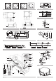
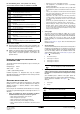
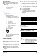
PREPARATIONS 1. 2. BEFORE INSTALLATION Relation of ceiling opening to unit and suspension bolt position. • • (See figure 3) ■ Make the ceiling opening needed for installation where applicable. (For existing ceilings.) 1 Refrigerant piping 2 Suspension bolt (x4) 3 Hanger bracket 4 False ceiling 5 Suspension bolt pitch 6 Indoor unit 7 Ceiling opening 8 Decoration panel • 3. Install the suspension bolts. (use either a W3/8 or M10 size bolt.
4. Check if the unit is horizontally levelled. • • 5. ■ When connecting the flare nut, coat the flare inner surface with ether oil or ester oil and initially tighten 3 or 4 turns by hand before tightening firmly. ■ If the refrigerant gas leaks during the work, ventilate the area. A toxic gas is emitted by the refrigerant gas being exposed to a fire. ■ Make sure there is no refrigerant gas leak.
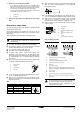
Cautions for brazing ■ - Be sure to carry out a nitrogen blow when brazing. Brazing without carrying out nitrogen replacement or releasing nitrogen into the piping will create large quantities of oxidized film on the inside of the pipes, adversely affecting valves and compressors in the refrigerating system and preventing normal operation. ■ 4 1 3 2 3 4 6 A-A' 5 4 mm When brazing while inserting nitrogen into the piping, nitrogen must be set to 0.
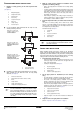
Testing of drain piping ■ A main switch or other means for disconnection, having a contact separation in all poles, must be incorporated in the fixed wiring in accordance with relevant local and national legislation. Note that the operation will restart automatically if the main power supply is turned off and then turned back on again. ■ This system consists of multiple indoor units. Mark each indoor unit as unit A, unit B...
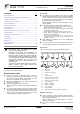
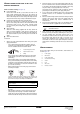
WIRING EXAMPLE AND HOW TO SET THE REMOTE CONTROLLER 2 Keep total current of crossover wiring between indoor units less than 12 A. Branch the line outside the terminal block of the unit in accordance with electrical equipment standards, when using two power wiring of a gauge greater than 2 mm 2 (Ø1.6). The branch must be sheathed in order to provide an equal or greater degree of insulation as power supply wiring itself.
See figures 13 and 15 Outdoor unit 2 Indoor unit 3 Remote controller (Optional accessories) 4 Most downstream indoor unit 5 For use with 2 remote controllers Second code No. (Note 2) Mode First No. code (Note 1) No. Description of setting 01 Filter contamination - Heavy/Light = Setting to define time between 2 filter cleaning display indications. (When Long-life contamination is filter high, setting can be changed to half the time inbetween 2 filter cleaning display indications.
Control by 2 Remote Controllers (Controlling 1 indoor unit by 2 remote controllers) When using 2 remote controllers, one must be set to "MAIN" and the other to "SUB". TEST Refer to the installation manual of the outdoor unit. NOTE Main/sub changeover 1. Insert a wedge-head screwdriver into the recess between the upper and lower part of the remote controller and, working from the 2 positions, pry off the upper part.
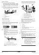
1 Open the suction grille (See figure 20) (action 1 in the illustration). Push both levers simultaneously in the direction of the arrow as indicated in the illustration and carefully lower the grille. (Identical procedure for closing.) 2 Remove the air filter (actions 2 to 4 in the illustration). Pull the air filter clip on both the bottom left and the right side of the filter toward you, and detach the filter. 3 Clean the air filter.
WIRING DIAGRAM Indoor unit Wired remote controller A1P,A2P .............. Printed circuit board R1T......................Thermistor (air) C1........................ Capacitor SS1......................Selector switch (MAIN/SUB) F1U ..................... Fuse (T, 5 A, 250 V) Receiver/display unit (attached to wireless remote controller) HAP..................... Light emitting diode (service monitor - green) A3P,A4P...............Printed circuit board KPR.....................
13 14 1 1 2 Control box IN/D OUT/D F1 F2 F1 F2 L N L N L N L N 4 LN P1 P2 F1 F2 T1 T2 LN P1 P2 F1 F2 T1 T2 LN P1 P2 F1 F2 T1 T2 LN P1 P2 F1 F2 T1 T2 2 7 P1 P2 P1 P2 P1 P2 P1 P2 8 3 13 14 1 15 16 1 Control box 2 IN/D OUT/D F1 F2 F1 F2 L N 4 LN P1 P2 F1 F2 T1 T2 LN P1 P2 F1 F2 T1 T2 LN P1 P2 F1 F2 T1 T2 LN P1 P2 F1 F2 T1 T2 2 3 SETTING P1 P2 P1 P2 P1 P2 5 3 4 15 16 19 S M 2 18 1 17 F2 T1 T2 S M 3 FORCED OFF 1 17 18 19 20 1 4 22 21 4 2+3 1 3
4PW56204-1 Copyright © Daikin