00_CV_3P171284-2D.
Low Voltage 2006/95/EC Electromagnetic Compatibility 2004/108/EC * Shinri Sada Manager Quality Control Department 1st. of Nov. 2008 FLKS25BVMB, FLKS35BVMB, FLXS25BVMB, FLXS35BVMB, FLK25BVMB, FLK35BVMB, FLX25BVMB, FLX35BVMB, FLKS50BVMB, FLKS60BVMB, FLXS50BVMB, FLXS60BVMB, FLKS25BAVMB, FLKS35BAVMB, FLKS50BAVMB, FLKS60BAVMB, FLXS25BAVMB, FLXS35BAVMB, FLXS50BAVMB, FLXS60BAVMB DAIKIN INDUSTRIES, LTD. Umeda Center Bldg.
01_EN_3P171284-2D.fm Page 1 Monday, August 23, 2010 2:33 PM Safety Precautions • Read these Safety Precautions carefully to ensure correct installation. • This manual classifies the precautions into WARNING and CAUTION. Be sure to follow all the precautions below: they are all important for ensuring safety. WARNING...............Failure to follow any of WARNING is likely to result in such grave consequences as death or serious injury. CAUTION...............
01_EN_3P171284-2D.
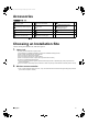
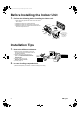
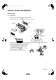
01_EN_3P171284-2D.fm Page 3 Monday, August 23, 2010 2:33 PM Before Installing the Indoor Unit 1. Perform the following before installing the indoor unit. 1) Open the air inlet grille and the screw cover, and remove the 7 screws. 2) Release the claws in the 3 places indicated. 3) Release the center hook and remove the front panel. 4) Release the claws in the 2 places indicated and remove the electric component cover.
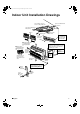
01_EN_3P171284-2D.fm Page 4 Monday, August 23, 2010 2:33 PM Indoor Unit Installation Drawings There should be no space between ceiling and the unit. Space for installation work Min. (200mm) Space for installation work Min. (200mm) 50mm or more from walls Air filters A Mounting plate The mounting plate should be installed on a wall which can support the weight of the indoor unit.
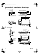
01_EN_3P171284-2D.fm Page 5 Monday, August 23, 2010 2:33 PM Indoor Unit Installation Drawings Ceiling mounting. Local drain pipe Rear side pipinghole ø65mm Ceiling 55 *1 more than 170 1. 40 Ceiling Wall 50 *1 Determine the position of the feed-through hole so that the local piping is placed in a downward sloping direction. Rear side drainhose hole ø40mm 1,050 40 138 40-45 Drain hose 490 Right side piping hole ø65mm 22 35 40 230 980 Wall 55 Top side piping hole ø65mm 2.
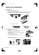
01_EN_3P171284-2D.fm Page 6 Monday, August 23, 2010 2:33 PM Indoor Unit Installation Ceiling Mounting 1. Installing the suspension bolt. 1) Install the suspension bolt so that it can support the indoor unit; adjust distance to ceiling before installation. 2) Mount the indoor unit according to the installation drawings and tighten it securely with M10 nut. (4 places) 3) After mounting the indoor unit on the ceiling, install each part as shown in the diagram on the right.
01_EN_3P171284-2D.fm Page 7 Monday, August 23, 2010 2:33 PM Indoor Unit Installation Wall Mounting 3. Installation. • Install the indoor unit on the wall according to the installation drawings. 1) Hang the indoor unit on the hooks of A mounting plate. (2 places) 2) Fix the three holes in the lower portion of the indoor unit with M4 × 25L screws.
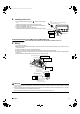
01_EN_3P171284-2D.fm Page 8 Monday, August 23, 2010 2:33 PM 4. Installing indoor unit. 1) Connect the extension auxiliary pipe ( M , supplied) to the local piping. (Applies to both ceiling mounting and wall mounting units.) 2) Prepare the local piping at the connection point for the drain pipe, as shown in the installation drawings. 3) Connect the drain hose to the local drain pipe. Position the interconnecting wire in the same direction as the piping.
01_EN_3P171284-2D.fm Page 9 Monday, August 23, 2010 2:33 PM Indoor Unit Installation 6. Insulation of refrigerant pipes. After checking for refrigerant leaks • Joints in liquid pipe and the gas pipe must be insulated with P heat insulation tube attached with Q binding bands. • Cut P heat insulation tube to appropriate length. Q Binding band P Heat insulation tube 7. Drain piping. 1) Connect the drain hose, as described below. Drain hose must slope downward. Allow no trap to form in the piping.
01_EN_3P171284-2D.fm Page 10 Monday, August 23, 2010 2:33 PM Refrigerant Piping Work With a Multi indoor unit , install as described in the installation manual supplied with the Multi outdoor unit. 1. Flaring the pipe end. (Cut exactly at right angles.) 1) Cut the pipe end with a pipe cutter. 2) Remove burrs with the cut surface facing downward so that the chips do not enter the pipe. 3) Put the flare nut on the pipe. 4) Flare the pipe. 5) Check that the flaring is properly made.
01_EN_3P171284-2D.fm Page 11 Monday, August 23, 2010 2:33 PM Refrigerant Piping Work 2-2. Selection of Copper and Heat Insulation materials • When using commercial copper pipes and fittings, observe the following: 1) Insulation material: Polyethylene foam Heat transfer rate: 0.041 to 0.052W/mK (0.035 to 0.045kcal/mh°C) Refrigerant gas pipe’s surface temperature reaches 110°C max. Choose heat insulation materials that will withstand this temperature.
01_EN_3P171284-2D.fm Page 12 Monday, August 23, 2010 2:33 PM Trial Operation and Testing 1. Trial operation and testing. 1-1 Measure the supply voltage and make sure that it falls in the specified range. 1-2 Trial operation should be carried out in either cooling or heating mode. ■ For Heat pump • In cooling mode, select the lowest programmable temperature; in heating mode, select the highest programmable temperature. 1) Trial operation may be disabled in either mode depending on the room temperature.
00_CV_3P171284-2D.fm Page 2 Monday, August 23, 2010 2:27 PM Two-dimensional bar code is a code for manufacturing.