Service manual
Manuals
Brands
Daikin Manuals
Air Conditioner
FLKS50BVMB
131
132
133
134
135
136
137
138
139
140
Indoor Unit
SiB
E05-3
12
122
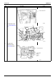
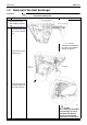
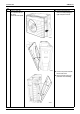
Rem
oval Procedu
re
4
The il
lust
rat
ion shows
the
contr
ol PCB (
indoor
unit)
.
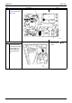
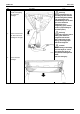
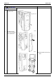
5
Disconnect t
he
termi
nals fr
om the
termin
al strip
boar
d.
Step
Procedure
Points
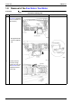
SW2
S7
S6
S24
JC
JB
JA
S37
S32
S26
S21
(R2958)
1
...
...
129
130
131
132
133
...
...
178