SiBE05-312 Service Manual Inverter Pair Floor / Ceiling Suspended Dual Type B-Series [Applied Models] zInverter Pair : Cooling Only zInverter Pair : Heat Pump zNon-Inverter Pair : Cooling Only
SiBE05-312 Inverter Pair B-Series zCooling Only Indoor Unit FLKS50BVMB Outdoor Unit RKS50BVMB RS50BVMB zHeat Pump Indoor Unit FLXS50BVMB Outdoor Unit RXS50BVMB Table of Contents i
SiBE05-312 1. Introduction .............................................................................................v 1.1 Safety Cautions ........................................................................................v Part 1 List of Functions ................................................................ 1 1. List of Functions ......................................................................................2 Part 2 Specifications ......................................................
SiBE05-312 Part 5 System Configuration....................................................... 41 1. System Configuration............................................................................42 2. Instruction..............................................................................................43 2.1 2.2 2.3 2.4 2.5 2.6 2.7 2.8 2.9 2.10 2.11 Safety Precautions .................................................................................43 Names of Parts.....................................
SiBE05-312 1.4 1.5 1.6 1.7 1.8 1.9 Removal of the Signal Receiver Unit / Swing Motor.............................118 Removal of the Discharge Grille...........................................................119 Removal of the Drain Pan ....................................................................120 Removal of the Electrical Box / PCB ....................................................121 Removal of the Fan Rotor / Fan Motor.................................................
SiBE05-312 Introduction 1. Introduction 1.1 Safety Cautions Cautions and Warnings Be sure to read the following safety cautions before conducting repair work. The caution items are classified into “ Warning” and “ Caution”. The “ Warning” items are especially important since they can lead to death or serious injury if they are not followed closely. The “ Caution” items can also lead to serious accidents under some conditions if they are not followed.
Introduction SiBE05-312 Caution Do not repair the electrical components with wet hands. Working on the equipment with wet hands can cause an electrical shock. Do not clean the air conditioner by splashing water. Washing the unit with water can cause an electrical shock. Be sure to provide the grounding when repairing the equipment in a humid or wet place, to avoid electrical shocks. Be sure to turn off the power switch and unplug the power cable when cleaning the equipment.
SiBE05-312 Introduction Warning Be sure to use an exclusive power circuit for the equipment, and follow the technical standards related to the electrical equipment, the internal wiring regulations and the instruction manual for installation when conducting electrical work. Insufficient power circuit capacity and improper electrical work can cause an electrical shock or fire. Be sure to use the specified cable to connect between the indoor and outdoor units.
Introduction SiBE05-312 Warning Do not use a joined power cable or extension cable, or share the same power outlet with other electrical appliances, since it can cause an electrical shock, excessive heat generation or fire. Caution Check to see if the parts and wires are mounted and connected properly, and if the connections at the soldered or crimped terminals are secure. Improper installation and connections can cause excessive heat generation, fire or an electrical shock.
SiBE05-312 Part 1 List of Functions 1. List of Functions ......................................................................................
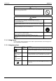
SiBE05-312 List of Functions { Operation Limit for Cooling (°CDB) –10 ~46 Basic Function Operation Limit for Heating (°CWB) — –15 ~18 PAM Control { { Compressor Comfortable Airflow Comfort Control Operation Lifestyle Convenience Health & Clean FLXS50BVMB RXS50BVMB { –10 ~46 Inverter (with Inverter Power Control) Category FLKS50BVMB RKS50BVMB Functions FLXS50BVMB RXS50BVMB Category FLKS50BVMB RKS50BVMB 1.
SiBE05-312 Inverter (with Inverter Power Control) Basic Function Compressor Comfortable Airflow Comfort Control Operation Lifestyle Convenience Category — Functions FLKS50BVMB RS50BVMB Functions FLKS50BVMB RS50BVMB Category List of Functions Air Purifying Filter with Bacteriostatic, Virustatic Functions { — Photocatalytic Deodorizing Filter { PAM Control — Air Purifying Filter with Photocatalytic Deodorizing Function — Oval Scroll Compressor — Swing Compressor { Rotary Compressor
List of Functions 4 SiBE05-312 List of Functions
SiBE05-312 Part 2 Specifications 1. Specifications ..........................................................................................6 1.1 Cooling Only.............................................................................................6 1.2 Heat Pump ...............................................................................................
Specifications SiBE05-312 1. Specifications 1.1 Cooling Only 230V, 50Hz Model Indoor Units Outdoor Units Capacity Rated (Min.~Max.) Moisture Removal Running Current (Rated) Power Consumption Rated (Min.~Max.
SiBE05-312 1.2 Specifications Heat Pump 230V, 50Hz Indoor Units Model Capacity Rated (Min.~Max.) Moisture Removal Running Current (Rated) Power Consumption Rated (Min.~Max.
Specifications 8 SiBE05-312 Specifications
SiBE05-312 Part 3 Printed Circuit Board Connector Wiring Diagram 1. Printed Circuit Board Connector Wiring Diagram..................................10 1.1 Indoor Unit..............................................................................................10 1.2 Outdoor Unit ...........................................................................................
Printed Circuit Board Connector Wiring Diagram SiBE05-312 1. Printed Circuit Board Connector Wiring Diagram 1.
SiBE05-312 PCB Detail Printed Circuit Board Connector Wiring Diagram PCB (1) : Control PCB (indoor unit) S21 SW2 S7 S26 S6 S32 S24 JC JB JA S37 (R2958) PCB (2) : Power Supply PCB (indoor unit) S36 FU1 V1 (R2959) PCB (3) : Display PCB LED3 LED2 PCB (4) : Signal Receiver PCB SW1 LED1 S25 S27 (R2960) S31(RTH) Printed Circuit Board Connector Wiring Diagram (R2961) 11
Printed Circuit Board Connector Wiring Diagram 1.
SiBE05-312 PCB Detail Printed Circuit Board Connector Wiring Diagram PCB (1) : Control PCB (outdoor unit) E AC1 FU2(3.
Printed Circuit Board Connector Wiring Diagram SiBE05-312 MID S34 S72 FU201 (3.
SiBE05-312 Part 4 Function and Control 1. Main Functions......................................................................................16 1.1 1.2 1.3 1.4 1.5 1.6 1.7 1.8 1.9 Frequency Principle................................................................................16 Auto-Swing .............................................................................................18 Fan Speed Control for Indoor Units........................................................19 Programme Dry Function ....
Main Functions SiBE05-312 1. Main Functions Note: 1.1 See the list of functions for the functions applicable to different models. Frequency Principle Main Control Parameters Additional Control Parameters Inverter Principle Drawing of Inverter The compressor is frequency-controlled during normal operation.
SiBE05-312 Inverter Features Main Functions The inverter provides the following features: The regulating capacity can be changed according to the changes in the outside temperature and cooling/heating load. Quick heating and quick cooling The compressor rotational speed is increased when starting the heating (or cooling). This enables a quick set temperature.
Main Functions 1.
SiBE05-312 1.3 Main Functions Fan Speed Control for Indoor Units Control Mode The airflow rate can be automatically controlled depending on the difference between the set temperature and the room temperature. This is done through phase control and hall IC control. For more information about hall IC, refer to the troubleshooting for fan motor on page 75. Phase Steps Phase control and fan speed control contains 9 steps: LLL, LL, SL, L, ML, M, MH, H and HH.
Main Functions 1.4 SiBE05-312 Programme Dry Function Programme dry function removes humidity while preventing the room temperature from lowering. Since the microcomputer controls both the temperature and air flow volume, the temperature adjustment and fan adjustment buttons are inoperable in this mode. In Case of Inverter Units The microcomputer automatically sets the temperature and fan settings.
SiBE05-312 1.5 Main Functions Automatic Operation Automatic Cooling / Heating Function (Heat Pump Only) When the AUTO mode is selected with the remote controller, the microcomputer automatically determines the operation mode from cooling and heating according to the room temperature and setting temperature at the time of the operation startup, and automatically operates in that mode.
Main Functions 1.6 SiBE05-312 Night Set Mode When the OFF timer is set, the Night Set circuit automatically activates. The Night Set circuit maintains the airflow setting made by users. The Night Set Circuit The Night Set circuit continues heating or cooling the room at the set temperature for the first one hour, then automatically lowers the temperature setting slightly in the case of cooling, or raises it slightly in the case of heating, for economical operations.
SiBE05-312 1.7 Main Functions Home Leave Operation Outline In order to respond to the customer's need for immediate heating and cooling of the room after returning home or for house care, a measure to switch the temperature and air volume from that for normal time over to outing time by one touch is provided. (This function responds also to the need for keeping up with weak cooling or heating.
Main Functions 1.8 SiBE05-312 Inverter Powerful Operation Outline In order to exploit the cooling and heating capacity to full extent, operate the air conditioner by increasing the indoor fan rotating speed and the compressor frequency. Details of the Control When Powerful button is pushed in each operation mode, the fan speed/setting temperature will be converted to the following states in a period of twenty minutes.
SiBE05-312 1.9 Main Functions Other Functions 1.9.1 Hot Start Function Heat Pump Only In order to prevent the cold air blast that normally comes when heating is started, the temperature of the heat exchanger of the indoor unit is detected, and either the air flow is stopped or is made very weak thereby carrying out comfortable heating of the room. *The cold air blast is also prevented using a similar control when the defrosting operation is started or when the thermostat gets turned ON. 1.9.
Function of Main Structural Parts SiBE05-312 2. Function of Main Structural Parts 2.1 Function of Thermistor 2.1.1 Heat Pump Model A Electrontic expansion valve C Four way valve B Compressor (R2827) A Outdoor Heat Exchanger Thermistor (DCB) 1. The outdoor heat exchanger thermistor is used for controlling target discharge temperature. Set a target discharge temperature depending on the outdoor and indoor heat exchanger temperature.
SiBE05-312 Function of Main Structural Parts 2.1.2 Cooling Only Model A Electrontic expansion valve C B Compressor (R2828) A Outdoor Heat Exchanger Thermistor (DCB) 1. The outdoor heat exchanger thermistor is used for controlling target discharge temperature. Set a target discharge temperature depending on the outdoor and indoor heat exchanger temperature. Control the electronic expansion valve opening so that the target discharge temperature can be obtained. 2.
Control Specification SiBE05-312 3. Control Specification 3.1 Mode Hierarchy Outline There are two modes; the mode selected in user’s place (normal air conditioning mode) and forced operation mode for installation and providing service. Detail 1.
SiBE05-312 3.2 Control Specification Frequency Control Outline Frequency will be determined according to the difference between room and set temperature. The function is explained as follows. 1. How to determine frequency. 2. Frequency command from an indoor unit. (The difference between a room temperature and the temperature set by the remote controller.) 3. Frequency command from an indoor unit. 4. Frequency initial setting. 5. PI control.
Control Specification SiBE05-312 3. Determine lower limit frequency Set a maximum value as an lower limit frequency among the frequency lower limits of the following functions: Pressure difference upkeep. 4. Determine prohibited frequency There is a certain prohibited frequency such as a power supply frequency.
SiBE05-312 3.3 Control Specification Controls at Mode Changing / Start-up 3.3.1 Preheating Operation Outline Operate the inverter in the open phase operation with the conditions including the preheating command (only for heat pump model) from the indoor, the outdoor air temperature and discharge pipe temperature. Detail Preheating ON Condition When outdoor air temperature is below 10.5ºC and discharge pipe temperature is below 10.5ºC, inverter in open phase operation starts.
Control Specification 3.4 SiBE05-312 Discharge Pipe Temperature Control Outline The discharge pipe temperature is used as the compressor's internal temperature. If the discharge pipe temperature rises above a certain level, the operating frequency upper limit is set to keep this temperature from going up further. Detail Divide the Zone A B A B C D C D 110 103 102 101 (R2836) Management within the Zones Zone Stop zone Drooping zone Unchanged zone Return / Reset zone 3.
SiBE05-312 3.6 Control Specification Freeze-up Protection Control Outline During cooling operation, the signals being sent from the indoor unit allow the operating frequency limitation and then prevent freezing of the indoor heat exchanger. (The signal from the indoor unit must be divided into the zones as the followings. Detail Conditions for Start Controlling Judge the controlling start with the indoor heat exchanger temperature after 2 sec from operation start. Control in Each Zone 3.
Control Specification 3.8 SiBE05-312 Fan Control Outline Fan control is carried out according to the following priority. 1. Fan ON control for electric component cooling fan 2. Fan control when defrosting 3. Fan OFF delay when stopped 4. ON/OFF control in cooling operation 5. Tap control when drooping function is working 6. Fan control in forced operation 7. Fan control in indoor / outdoor unit silent operation 8. Fan control in powerful mode 9.
SiBE05-312 Control Specification 3.10 Low Hz High Pressure Limit Outline Heat Pump Only Set the upper limit of high pressure in a low Hz zone. Set the upper limit of the indoor heat exchanger temperature by its operating frequency of Hz. Separate into three zones, reset zone, unchanged zone and drooping zone and the frequency control must be carried out in such zones. Detail Separate into Zones Note: Drooping: The system stops 2 minutes after staying in the drooping zone. 3.
Control Specification SiBE05-312 3.12 Electronic Expansion Valve Control Detail The followings are the examples of control which function in each mode by the electronic expansion valve control. Operation pattern Control for abnormally high discharge pipe temperature The following items are included in the electronic expansion valve control. Electronic expansion valve is fully closed 1. Electronic expansion valve is fully closed when turning on the power. 2. Pressure equalizing control Open Control 1.
SiBE05-312 Control Specification 3.12.1 Fully Closing with Power ON Initialize the electronic expansion valve when turning on the power, set the opening position and develop pressure equalizing. 3.12.2 Pressure Equalization Control When the compressor is stopped, open and close the electronic expansion valve and develop pressure equalization. 3.12.3 Opening Limit Outline Limit a maximum and minimum opening of the electronic expansion valve.
Control Specification SiBE05-312 3.12.7 Control when frequency is changed When the target discharge pipe temperature control is active, if the target frequency is changed for a specified value in a certain time period, cancel the target discharge pipe temperature control and change the target opening of the electronic expansion valve according to the shift. 3.12.
SiBE05-312 Control Specification 3.13 Malfunctions 3.13.1 Sensor Malfunction Detection Sensor malfunction may occur either in the thermistor or current transformer (CT) system. Relating to Thermistor Malfunction 1. Outdoor heat exchanger thermistor 2. Discharge pipe thermistor 3. Fin thermistor 4. Outside air thermistor Relating to CT Malfunction When the output frequency is more than 55 Hz and the input current is less than 1.25A, carry out abnormal adjustment. 3.13.
Control Specification SiBE05-312 3.14 Forced Operation Mode Outline Forced operating mode includes only forced cooling. Detail Forced Cooling Item Forced operation allowing conditions Starting/adjustment Forced Cooling 1) The outdoor unit is not abnormal and not in the 3-minute stand-by mode. 2) The operating mode of the outdoor unit is the stop mode. 3) The forced operation is ON. The forced operation is allowed when the above “and” conditions are met.
SiBE05-312 Part 5 System Configuration 1. System Configuration............................................................................42 2. Instruction..............................................................................................43 2.1 2.2 2.3 2.4 2.5 2.6 2.7 2.8 2.9 2.10 2.11 System Configuration Safety Precautions .................................................................................43 Names of Parts.........................................................................
System Configuration SiBE05-312 1. System Configuration After the installation and test operation of the room air conditioner have been completed, it should be operated and handled as described below. Every user would like to know the correct method of operation of the room air conditioner, to check if it is capable of cooling (or heating) well, and to know a clever method of using it.
SiBE05-312 Instruction 2. Instruction 2.1 Safety Precautions • • • • Keep this manual where the operator can easily find them. Read this manual attentively before starting up the unit. For safety reason the operator must read the following cautions carefully. This manual classifies precautions into WARNINGS and CAUTIONS. Be sure to follow all precautions below: they are all important for ensuring safety.
Instruction SiBE05-312 • Do not stand or sit on the outdoor unit. Do not place any object on the unit to avoid injury, do not remove the fan guard. • Do not place anything under the indoor or outdoor unit that must be kept away from moisture. In certain conditions, moisture in the air may condense and drip. • After a long use, check the unit stand and fittings for damage. • Do not touch the air inlet and alminum fins of outdoor unit. It may cause injury.
SiBE05-312 2.2 Instruction Names of Parts ■ Indoor Unit The indoor unit can be installed either to the ceiling or to a wall. The descriptions contained in this manual show the case when installation is being carried out to the ceiling. (The methods of operation used are the same when installing to a wall.
Instruction SiBE05-312 ■ Outdoor Unit 15 17 18 19 16 ■ Indoor Unit 1. Louvres (vertical blades): The louvres are inside of the air outlet. (page 12.) 2. Air outlet 3. Flap (horizontal blade): (page 12.) 13. Indoor unit ON/OFF switch: (page 10.) • Push this switch once to start operation. Push once again to stop it. • The operation mode refers to the following table. 4. Grille tab 5. Air inlet FLKS FLXS 6. Display 7. Air filter 8.
SiBE05-312 Instruction ■ Remote Controller 1 ON 2 C 5 HOME LEAVE ON/OFF 3 POWERFUL TEMP 6 4 7 MODE SILENT FAN SWING 9 10 CANCEL 14 8 ON 11 15 OFF TIMER 13 12 < ARC433A5, A6 > 1. Signal transmitter: • It sends signals to the indoor unit. 2. Display: • It displays the current settings. (In this illustration, each section is shown with all its displays ON for the purpose of explanation.) 3. HOME LEAVE button: for HOME LEAVE operation (page 16.) 4.
Instruction 2.3 SiBE05-312 Preparation before Operation ■ To set the batteries 1. Press with a finger and slide the front cover to take it off. Position + and – correctly! 2 – + + 2. Set two dry batteries (AAA). – 3. Set the front cover as before. 3 1 ATTENTION ■ About batteries • When replacing the batteries, use batteries of the same type, and replace the two old batteries together. • When the system is not used for a long time, take the batteries out.
SiBE05-312 Instruction ■ To operate the remote controller • To use the remote controller, aim the transmitter at the indoor unit. If there is anything to block signals between the unit and the remote controller, such as a curtain, the unit will not operate. • Do not drop the remote controller. Do not get it wet. • The maximum distance for communication is about 4 m. ON OFF Receiver ■ To fix the remote controller holder on the wall 1. Choose a place from where the signals reach the unit.
Instruction SiBE05-312 ■ To set the clock 1. Press “CLOCK button”. is displayed. C blinks. 2. Press “TIMER setting button” to set the clock to the present time. Holding down “ ” or “ ” button rapidly increases or decreases the time display. 3. Press “CLOCK button”. blinks. ■ Turn the breaker ON • Turning ON the breaker opens the flap, then closes it again. (This is a normal procedure.) HOME LEAVE ON/OFF POWERFUL TEMP MODE SILENT FAN ON SWING 2 CANCEL 1.
SiBE05-312 2.4 Instruction AUTO · DRY · COOL · HEAT · FAN Operation The air conditioner operates with the operation mode of your choice. From the next time on, the air conditioner will operate with the same operation mode. ■ To start operation C 1. Press “MODE selector button” and select a operation mode. • Each pressing of the button advances the mode setting in sequence.
Instruction SiBE05-312 ■ To change the air flow rate setting 5. Press “FAN setting button”. DRY mode AUTO or COOL or HEAT or FAN mode Five levels of air flow rate setting from “ plus “ ”“ ” to “ ” ” are available. The air flow rate setting is not variable. • Indoor unit quiet operation When the air flow is set to “ ”, the noise from the indoor unit will become quieter. Use this when making the noise quieter. The unit might lose power when the fan strength is set to a weak level.
SiBE05-312 2.5 Instruction Adjusting the Air Flow Direction You can adjust the air flow direction to increase your comfort. ■ To adjust the horizontal blade (flap) ON C 1. Press “SWING button”. The display will light up and the flaps will begin to swing. 2. When the flaps have reached the desired position, press “SWING button” once more. The display will go blank. The flaps will stop moving.
Instruction SiBE05-312 ■ To adjust the vertical blades (louvres) • When adjusting the louvre, use a robust and stable stool and watch your steps carefully. Hold the knob and move the louvres. (You will find a knob on the left side and the right side blades.) Notes on flap and louvres angles • Unless [SWING] is selected, you should set the flap at a near- horizontal angle in COOL or DRY mode to obtain the best performance.
SiBE05-312 2.6 Instruction POWERFUL Operation POWERFUL operation quickly maximizes the cooling (heating) effect in any operation mode. You can get the maximum capacity . ■ To start POWERFUL operation ON 1. Press “POWERFUL button”. • POWERFUL operation ends in 20 minutes. Then the system automatically operates again with the settings which were used before POWERFUL operation. • When using POWERFUL operation, there are some functions which are not available.
Instruction 2.7 SiBE05-312 OUTDOOR UNIT SILENT Operation OUTDOOR UNIT SILENT operation lowers the noise level of the outdoor unit by changing the frequency and fan speed on the outdoor unit. This function is convenient during night. ■ To start OUTDOOR UNIT SILENT operation C 1. Press “SILENT button”. ■ To cancel OUTDOOR UNIT SILENT operation 2. Press “SILENT button” again.
SiBE05-312 2.8 Instruction HOME LEAVE Operation HOME LEAVE operation is a function which allows you to record your preferred temperature and air flow rate settings. ■ To start HOME LEAVE operation 1. Press “HOME LEAVE button” . C • The HOME LEAVE lamp lights up. ■ To cancel HOME LEAVE operation 1, 2 HOME LEAVE ON/OFF POWERFUL TEMP MODE SILENT FAN 2. Press “HOME LEAVE button” again. • The HOME LEAVE lamp goes off. ON SWING CANCEL OFF TIMER Before using HOME LEAVE operation.
Instruction SiBE05-312 ■ What’s the HOME LEAVE operation Is there a set temperature and air flow rate which is most comfortable, a set temperature and air flow rate which you use the most? HOME LEAVE operation is a function that allows you to record your favorite set temperature and air flow rate. You can start your favorite operation mode simply by pressing the HOME LEAVE button on the remote controller. This function is convenient in the following situations. ■ Useful in these cases. 1.
SiBE05-312 2.9 Instruction TIMER Operation Timer functions are useful for automatically switching the air conditioner on or off at night or in the morning. You can also use OFF TIMER and ON TIMER in combination. ■ To use OFF TIMER operation C • Check that the clock is correct. If not, set the clock to the present time. (page 9.) HOME LEAVE ON/OFF 1. Press “OFF TIMER button”. POWERFUL TEMP MODE SILENT FAN is displayed. blinks. 2.
Instruction SiBE05-312 ■ To use ON TIMER operation • Check that the clock is correct. If not, set the clock to the present time (page 9.). 1. Press “ON TIMER button”. C is displayed. blinks. 2. Press “TIMER Setting button” until the time setting reaches the point you like. • Every pressing of either button increases or decreases the time setting by 10 minutes. Holding down either button changes the setting rapidly. 3. Press “ON TIMER button” again. • The TIMER lamp lights up.
SiBE05-312 Instruction 2.10 Care and Cleaning CAUTION Before cleaning, be sure to stop the operation and turn the breaker OFF. Units ■ Indoor unit, Outdoor unit and Remote controller 1. Wipe them with dry soft cloth. ■ Front grille 1. Open the front grille. • Hold the grille by the tabs on the two sides and lift it unitl it stops. 2. Clean the front grille • Wipe it with a soft cloth soaked in water. • Only neutral detergent may be used.
Instruction SiBE05-312 Filters 1. Open the front grille. (page 22) 2. Pull out the air filters. • Push upwards the tab at the center of each air filter, then pull it down. 3. Take off the air purifying filter, photocatalytic deodorizing filter. • Hold the recessed parts of the frame and unhook the four claws. 4. Clean or replace each filter. See below. Air purifying filter or Photocatalytic deodorizing filter 5.
SiBE05-312 Instruction Check Check that the base, stand and other fittings of the outdoor unit are not decayed or corroded. Check that nothing blocks the air inlets and the outlets of the indoor unit and the outdoor unit. Check that the earth wire is not disconnected or broken. Check that the drain comes smoothly out of the drain hose during COOL or DRY operation. • If no drain water is seen, water may be leaking from the indoor unit. Stop operation and consult the service shop if this is the case.
Instruction SiBE05-312 2.11 Troubleshooting These cases are not troubles. The following cases are not air conditioner troubles but have some reasons. You may just continue using it. Case Explanation Operation does not start soon. • When ON/OFF button was pressed soon after operation was stopped. • When the mode was reselected. • This is to protect the air conditioner. You should wait for about 3 minutes. Hot air does not flow out soon after the start of heating operation.
SiBE05-312 Instruction Check again. Please check again before calling a repair person. Case The air conditioner does not operate. (OPERATION lamp is off) Check • • • • Hasn’t a breaker turned OFF or a fuse blown? Isn’t it a power failure? Are batteries set in the remote controller? Is the timer setting correct? Cooling (Heating) effect is poor.
Instruction SiBE05-312 Call the service shop immediately. WARNING ■When an abnormality (such as a burning smell) occurs, stop operation and turn the breaker OFF. Continued operation in an abnormal condition may result in troubles, electric shocks or fire. Consult the service shop where you bought the air conditioner. ■Do not attempt to repair or modify the air conditioner by yourself. Incorrect work may result in electric shocks or fire. Consult the service shop where you bought the air conditioner.
SiBE05-312 Part 6 Service Diagnosis 1. 2. 3. 4. Caution for Diagnosis............................................................................68 Problem Symptoms and Measures .......................................................69 Service Check Function ........................................................................70 Troubleshooting ....................................................................................71 4.1 4.2 4.3 4.4 4.5 4.6 4.7 4.8 4.9 4.10 4.11 4.12 4.13 4.14 4.15 4.16 4.
Caution for Diagnosis SiBE05-312 1. Caution for Diagnosis The Operation lamp flashes when any of the following errors is detected. 1. When a protection device of the indoor or outdoor unit is activated or when the thermistor malfunctions, disabling equipment operation. 2. When a signal transmission error occurs between the indoor and outdoor units. In either case, conduct the diagnostic procedure described in the following pages.
SiBE05-312 Problem Symptoms and Measures 2. Problem Symptoms and Measures Symptom Check Item None of the units operates. Check the power supply. Check the type of the indoor units. Check the outdoor air temperature. Diagnosis with remote controller indication Check the remote controller addresses. Operation sometimes stops. Check the power supply. Check the outdoor air temperature.
Service Check Function SiBE05-312 3. Service Check Function In the ARC433A series remote controller, the temperature display sections on the main unit indicate corresponding codes. 1. When the timer cancel button is held down for 5 seconds, a “00” indication flashes on the temperature display section. ON C HOME LEAVE POWERFUL MODE SILENT ON/OFF TEMP FAN ON SWING CANCEL TIMER CANCEL button It cancels the timer setting. OFF TIMER < ARC433A5, A6 > (R2975) 2.
SiBE05-312 Troubleshooting 4. Troubleshooting 4.
Troubleshooting 4.2 SiBE05-312 Indoor Unit PCB Abnormality Remote Controller Display A1 Method of Malfunction Detection Evaluation of zero-cross detection of power supply by indoor unit. Malfunction Decision Conditions When there is no zero-cross detection in approximately 10 continuous seconds. Supposed Causes Faulty indoor unit PCB Faulty connector connection Troubleshooting Caution Be sure to turn off power switch before connect or disconnect connector, or parts damage may be occurred.
SiBE05-312 4.3 Troubleshooting Freeze-up Protection Control or High Pressure Control Remote Controller Display A5 Method of Malfunction Detection High pressure control (heat pump model only) Malfunction Decision Conditions High pressure control During heating operations, the temperature detected by the indoor heat exchanger thermistor is used for the high pressure control (stop, outdoor fan stop, etc.
Troubleshooting SiBE05-312 Troubleshooting Caution Check No.6 Refer to P.104 Be sure to turn off power switch before connect or disconnect connector, or parts damage may be occurred. Check the air passage. Is there any short-circuit? YES Provide sufficient air passage. NO Check the intake air filter. Is it very dirty? YES Clean the air filter. NO Check the dust accumulation on the indoor unit heat exchanger. Is it very dirty? YES Clean the heat exchanger. NO Check No.
SiBE05-312 4.4 Troubleshooting Fan Motor (AC Motor) or Related Abnormality Remote Controller Display A6 Method of Malfunction Detection The rotation speed detected by the hall IC during fan motor operation is used to determine abnormal fan motor operation. Malfunction Decision Conditions When the detected rotation speed is less than 50% of the HH tap under maximum fan motor rotation demand. Supposed Causes ! ! ! ! ! Operation halt due to short circuit inside the fan motor winding.
Troubleshooting 4.5 SiBE05-312 Thermistor or Related Abnormality (Indoor Unit) Remote Controller Display C4, C9 Method of Malfunction Detection The temperatures detected by the thermistors are used to determine thermistor errors. Malfunction Decision Conditions When the thermistor input is more than 4.96 V or less than 0.04 V during compressor operation∗. ∗ (reference) When above about 212°C (less than 120 ohms) or below about -50°C (more than 1,860 kohms).
SiBE05-312 4.6 Troubleshooting Signal Transmission Error (between Indoor and Outdoor Units) Remote Controller Display U4 Method of Malfunction Detection The data received from the outdoor unit in indoor unit-outdoor unit signal transmission is checked whether it is normal. Malfunction Decision Conditions When the data sent from the outdoor unit cannot be received normally, or when the content of the data is abnormal. Supposed Causes Faulty outdoor unit PCB. Faulty indoor unit PCB.
Troubleshooting 4.7 SiBE05-312 OL Activation (Compressor Overload) Remote Controller Display E5 Method of Malfunction Detection A compressor overload is detected through compressor OL. Malfunction Decision Conditions If the compressor OL is activated twice, the system will be shut down. The error counter will reset itself if this or any other error does not occur during the following Supposed Causes 60-minute compressor running time (total time).
SiBE05-312 4.8 Troubleshooting Compressor Lock Remote Controller Display E6 Method of Malfunction Detection A compressor lock is detected by checking the compressor running condition through the position detection circuit. Malfunction Decision Conditions The position detection circuit detects a compressor frequency of below 10 Hz for 20 seconds or a frequency of above 160 Hz.
Troubleshooting 4.9 SiBE05-312 DC Fan Lock Remote Controller Display E7 Method of Malfunction Detection A fan motor or related error is detected by checking the high-voltage fan motor rpm being detected by the hall IC. Malfunction Decision Conditions The fan does not start in 30 seconds even when the fan motor is running. The system will be shut down if the error occurs 16 times.
SiBE05-312 Troubleshooting 4.10 Input Over Current Detection Remote Controller Display E8 Method of Malfunction Detection An input over-current is detected by checking the input current value being detected by CT with the compressor running. Malfunction Decision Conditions The following CT input with the compressor running continues for 2.5 seconds. Supposed Causes Service Diagnosis CT input Above : 20 A The system will be shut down if the error occurs 16 times.
Troubleshooting SiBE05-312 Troubleshooting Caution Check No.7 Refer to P.105 Check No.8 Refer to P.106 Be sure to turn off power switch before connect or disconnect connector, or parts damage may be occurred. ∗ An input over-current may result from wrong internal wiring. If the wires have been disconnected and reconnected for part replacement, for example, and the system is interrupted by an input over-current, take the following procedure. Get restarted and measure the input current.
SiBE05-312 Troubleshooting 4.11 Four Way Valve Abnormality Remote Controller Display EA Method of Malfunction Detection The room temperature thermistor, the indoor unit heat exchanger thermistor, the outdoor temperature thermistor and the outdoor unit heat exchanger thermistor are checked to see if they function within their normal ranges in the operating mode.
Troubleshooting SiBE05-312 Troubleshooting Caution Check No.5 Refer to P.103 Check No.6 Refer to P.104 Be sure to turn off power switch before connect or disconnect connector, or parts damage may be occurred. Four way valve coil disconnected (loose)? YES NO YES Harness out of connector? Check No.11 Refer to P.107 Correct. Reconnect. NO Check the continuity of the four way valve coil and harness. Disconnect the harness from the connector.
SiBE05-312 Troubleshooting 4.12 Discharge Pipe Temperature Control Remote Controller Display F3 Method of Malfunction Detection The discharge pipe temperature control (stop, frequency drooping, etc.) is checked with the temperature being detected by the discharge pipe thermistor. Malfunction Decision Conditions If a stop takes place 6 times successively due to abnormal discharge pipe temperature, the system will be shut down.
Troubleshooting SiBE05-312 4.13 Position Sensor Abnormality Remote Controller Display H6 Method of Malfunction Detection A compressor startup failure is detected by checking the compressor running condition through the position detection circuit. Malfunction Decision Conditions The compressor fails to start in about 15 seconds after the compressor run command signal Supposed Causes Compressor relay cable disconnected is sent.
SiBE05-312 Troubleshooting 4.14 CT or Related Abnormality Remote Controller Display H8 Method of Malfunction Detection A CT or related error is detected by checking the compressor running frequency and CTdetected input current. Malfunction Decision Conditions The compressor running frequency is below 55 Hz and the CT input is below 0.1 V. (The input current is also below 1.25 A.) If this error repeats 4 times, the system will be shut down.
Troubleshooting SiBE05-312 Troubleshooting Caution Check No.12 Refer to P.108 Be sure to turn off power switch before connect or disconnect connector, or parts damage may be occurred. Turn off the power and turn it on again. Get the system started. ∗ Running current as shown at right with relay cable 1 or 2? YES Current (guideline) NO Check No. 12 Check the capacitor voltage. Rising with increasing frequency 2 sec DC380±30V? Replace the outdoor unit PCB.
SiBE05-312 Troubleshooting 4.15 Thermistor or Related Abnormality (Outdoor Unit) Remote Controller Display P4, J3, J6, H9 Method of Malfunction Detection This type of error is detected by checking the thermistor input voltage to the microcomputer. [A thermistor error is detected by checking the temperature.] Malfunction Decision Conditions The thermistor input is above 4.96 V or below 0.04 V with the power on.
Troubleshooting SiBE05-312 Troubleshooting Caution Check No.6 Refer to P.104 Be sure to turn off power switch before connect or disconnect connector, or parts damage may be occurred. Turn on the power again. Error displayed again on remote controller? NO Reconnect. YES Connector or thermistor disconnected? YES Reconnect. NO Check No. 6 Check the thermistor resistance value. NO Normal? YES Replace defective one(s) of the following thermistors.
SiBE05-312 Troubleshooting 4.16 Electrical Box Temperature Rise Remote Controller Display L3 Method of Malfunction Detection An electrical box temperature rise is detected by checking the radiation fin thermistor with the compressor off. Malfunction Decision Conditions With the compressor off, the radiation fin temperature is above 80°C (above 75°C in the case of 7.1kW class). (Reset is made when the temperature drops below 70°C.
Troubleshooting SiBE05-312 Troubleshooting Caution Check No.6 Refer to P.104 Be sure to turn off power switch before connect or disconnect connector, or parts damage may be occurred. Turn off the power and turn it on again. Check No.7 Refer to P.105 Error again or outdoor unit fan activated? Check No.9 Refer to P.106 WARNING To cool down the electricals, the outdoor unit fan gets started when the radiation fin temperature rises above 78˚C and stops itself when it drops below 70˚C. YES NO Check No.
SiBE05-312 Troubleshooting 4.17 Radiation Fin Temperature Rise Remote Controller Display L4 Method of Malfunction Detection A radiation fin temperature rise is detected by checking the radiation fin thermistor with the compressor on. Malfunction Decision Conditions Supposed Causes Service Diagnosis If the radiation fin temperature with the compressor on is above 90°C, If a radiation fin temperature rise takes place 4 times successively, the system will be shut down.
Troubleshooting SiBE05-312 Troubleshooting Check No.6 Refer to P.104 Caution Be sure to turn off power switch before connect or disconnect connector, or parts damage may be occurred. Turn off the power and turn it on again to get the system started. Check No.7 Refer to P.105 Error displayed again? Check No.9 Refer to P.106 YES NO Check No. 6 Check the thermistor resistance value. l Fin thermistor Check the radiation fin temperature.
SiBE05-312 Troubleshooting 4.18 Output Over Current Detection Remote Controller Display L5 Method of Malfunction Detection An output over-current is detected by checking the current that flows in the inverter DC section. Malfunction Decision Conditions A position signal error occurs while the compressor is running. A speed error occurs while the compressor is running. An output over-current input is fed from the output over-current detection circuit to the microcomputer.
Troubleshooting SiBE05-312 Troubleshooting Caution Check No.7 Refer to P.105 Be sure to turn off power switch before connect or disconnect connector, or parts damage may be occurred. ∗ An output over-current may result from wrong internal wiring. If the wires have been disconnected and reconnected for part replacement, for example, and the system is interrupted by an output over-current, take the following procedure. NO Stop valve fully open? Check No.8 Refer to P.106 Check No.13 Refer to P.
SiBE05-312 Troubleshooting 4.19 Insufficient Gas Remote Controller Display U0 Method of Malfunction Detection Gas shortage detection I : A gas shortage is detected by checking the CT-detected input current value and the compressor running frequency. Gas shortage detection II : A gas shortage is detected by checking the difference between indoor unit heat exchanger temperature and room temperature as well as the difference between outdoor unit heat exchanger temperature and room temperature.
Troubleshooting SiBE05-312 Troubleshooting Caution Check No.4 Refer to P.102 Check No.6 Refer to P.104 Be sure to turn off power switch before connect or disconnect connector, or parts damage may be occurred. Any thermistor disconnected? NO YES Reconnect in position. * Discharge pipe thermistor * Indoor / outdoor unit heat exchanger thermistor * Room temperature thermistor * Outdoor air thermistor YES Open the stop valve. Stop valve closed? NO Check for gas leakage.
SiBE05-312 Troubleshooting 4.20 Low-voltage Detection Remote Controller Display U2 Method of Malfunction Detection An abnormal voltage rise or drop is detected by checking the detection circuit or DC voltage detection circuit.
Troubleshooting SiBE05-312 4.21 High Pressure Control in Cooling Remote Controller Display F6 Method of Malfunction Detection High-pressure control (stop, frequency drop, etc.) is activated in the cooling mode if the temperature being sensed by the heat exchanger thermistor exceeds the limit. Malfunction Decision Conditions Activated when the temperature being sensed by the heat exchanger thermistor rises above 60°C. (Deactivated when the said temperature drops below 50°C.
SiBE05-312 Troubleshooting Troubleshooting Caution Check No.4 Refer to P.102 Check No.6 Refer to P.104 Be sure to turn off power switch before connect or disconnect connector, or parts damage may be occurred. Check the installation space. Check No.7 Installation condition check Abnormal Normal Check No.7 Refer to P.105 Check No.9 Outdoor fan check Abnormal Normal Check No.9 Refer to P.106 Change the air outlet grille position. Change the installation location. Clean the heat exchanger.
Check SiBE05-312 5. Check 5.1 How to Check 5.1.1 Electronic Expansion Valve Check Check No.4 Conduct the followings to check the electronic expansion valve (EV). 1. Check to see if the EV connector is correctly inserted in the PCB. Compare the EV unit and the connector number. 2. Turn the power off and back on again, and check to see if all the EVs generate latching sound. 3.
SiBE05-312 Check 5.1.2 Four Way Valve Performance Check Check No.5 Turn off the power and turn it on again. Start the heating-mode run. S80 voltage at DC 180-220 V with compressor on? (Fig. 1) ∗ Four way valve coil Cooling / dry : No continuity Heating : Continuity NO Replace the outdoor unit PCB. YES Disconnect the four way valve coil from the connector and check the continuity. Four way valve coil resistance at 1500 ohms? NO YES Replace the four way valve coil. Replace the four way valve.
Check SiBE05-312 5.1.3 Thermistor Resistance Check Check No.6 Remove the connectors of the thermistors on the PCB, and measure the resistance of each thermistor using tester. The relationship between normal temperature and resistance is shown in the graph and the table below. Thermistor R25°C=20kΩ B=3950 104 Temperature (°C) -20 211.0 (kΩ) -15 -10 150 116.5 -5 0 88 67.2 5 10 51.9 40 15 20 31.8 25 25 30 20 16 35 40 13 10.6 45 50 8.7 7.
SiBE05-312 Check 5.1.4 Installation Condition Check Check No.7 Installation condition check Check the allowable dimensions of the air suction and discharge area. Normal Does the discharged air from other outdoor unit cause an increase of the suction air temperature? Abnormal YES Change the position of the air discharge grille or the installation location. Change the position of the air discharge grille or the installation location.
Check SiBE05-312 5.1.5 Discharge Pressure Check Check No.8 Discharge pressure check NO High Replace compessor. YES Is the stop valve open? NO Open the stop valve. YES Is the connection pipe deformed? NO Replace the pipe installed at the site. YES At the heat exchanger and air filter dirty? NO Clean. YES Replace the compressor. (R1443) 5.1.6 Outdoor Unit Fan System Check (With DC Motor) Check No.9 Check the outdoor unit fan system.
SiBE05-312 Check 5.1.7 Power Supply Waveforms Check Check No.10 Measure the power supply waveform between pins 1 and 3 on the terminal board, and check the waveform disturbance. Check to see if the power supply waveform is a sine wave (Fig.1). Check to see if there is waveform disturbance near the zero cross (sections circled in Fig.2) [Fig.1] [Fig.2] 5.1.8 Inverter Units Refrigerant System Check Check No.
Check SiBE05-312 5.1.9 Capacitor Voltage Check Check No.12 Before this checking, be sure to check the main circuit for short-circuit. Checking the capacitor voltage z With the circuit breaker still on, measure the voltage according to the drawing of the model in question. Be careful never to touch any live parts. Use the tester in the DC range.
SiBE05-312 Check 5.1.11 Main Circuit Electrolytic Capacitor Check Check No.14 Checking the main circuit electrolytic capacitor z Never touch any live parts for at least 10 minutes after turning off the circuit breaker. z If unavoidably necessary to touch a live part, make sure there is no DC voltage using the tester. z Check the continuity with the tester. Reverse the pins and make sure there is continuity. 5.1.12 Turning Speed Pulse Input on the Outdoor Unit PCB Check Check No.
Check SiBE05-312 5.1.13 Hall IC Check Check No.16 1. Check the connector connection. 2. With the power ON, operation OFF, and the connector connected, check the following. *Output voltage of about 5 V between pins 1 and 3. *Generation of 3 pulses between pins 2 and 3 when the fan motor is operating. Failure of (1) → faulty PCB → Replace the PCB. Failure of (2) → faulty hall IC → Replace the fan motor. Both (1) and (2) result → Replace the PCB.
SiBE05-312 Part 7 Removal Procedure 1. Indoor Unit...........................................................................................112 1.1 1.2 1.3 1.4 1.5 1.6 1.7 1.8 1.9 Removal of the Air Filter / Front Grille ..................................................112 Removal of the Front Panel..................................................................115 Removal of the Horizontal Blade..........................................................
Indoor Unit SiBE05-312 1. Indoor Unit 1.1 Removal of the Air Filter / Front Grille Procedure Step Warning Be sure to wait 10 minutes or more after turning off all power supplies before disassembling work. Procedure Points 1. Features Ceiling-suspended type and floormounted type are provided. Explanation will be given by taking the ceiling-suspended type as an example.
SiBE05-312 Step Indoor Unit Procedure 2 Holding the tab at the center of filter frame, pull the air filter forward. 3 Remove the air filter by pulling along the slide guide. Points Installing filters can be done easily by sliding-in along the slide guide. 3. Remove the front grille. 1 Disengage the two hooks (left and right sides), using screw driver.
Indoor Unit Step 2 SiBE05-312 Procedure Points To remove the front grille, disengage hooks at three locations. 4. Remove the side panel cover. 1 Remove the side panel cover for removing of suspension parts. Note: If it is difficult to remove side panel from outside with finger, remove front panel first, then push side panel from inside of unit to outside.
SiBE05-312 1.2 Removal of the Front Panel Procedure Step 1 Indoor Unit Warning Be sure to wait 10 minutes or more after turning off all power supplies before disassembling work. Procedure Points Remove the four screws located at the back of the front panel. Note: For the ceiling-suspended type, remove drain hose before removing the screws. 2 Remove the three screw covers at the front of the front panel. 3 Remove the three screws.
Indoor Unit Step SiBE05-312 Procedure 4 Disengage the three hooks of the front panel located at discharge port. 5 Press A-section slightly at the center of the front panel, and disengage hook. 6 Remove the front panel. Points Caution For ceiling-suspended type, be careful that the front panel may fall when hooks are disengaged. To prevent the front panel from falling down, this service work should be done by two persons.
SiBE05-312 1.3 Indoor Unit Removal of the Horizontal Blade Procedure Step Warning Be sure to wait 10 minutes or more after turning off all power supplies before disassembling work. Procedure 1 Open the horizontal blade. 2 Deflect the three center bearings to left side slightly, and disengage shaft of blade. 3 Bend the blade slightly to disengage shafts from bearings at both ends. (Remove the left side shaft first.
Indoor Unit 1.4 SiBE05-312 Removal of the Signal Receiver Unit / Swing Motor Procedure Step Warning Be sure to wait 10 minutes or more after turning off all power supplies before disassembling work. Procedure Points 1. Remove the signal receiver unit. 1 Disengage the two hooks (left and right sides) to remove the signal receiver unit. 2 Remove the wire harness of the signal receiver from the groove. Note: Rearrange the wire harness in position as it was when reassembling signal receiver unit. 2.
SiBE05-312 1.5 Indoor Unit Removal of the Discharge Grille Procedure Step Warning Be sure to wait 10 minutes or more after turning off all power supplies before disassembling work. Procedure 1 Remove the two screws securing discharge grille. 2 Disengage the two hooks (left and right sides) and remove the discharge grille by pulling forward.
Indoor Unit 1.6 Removal of the Drain Pan Procedure Step 1 Warning Be sure to wait 10 minutes or more after turning off all power supplies before disassembling work. Procedure Disconnect the drain hose. 2 Remove the three screws securing the suction side of the drain pan. 3 Disengage the two hooks located at both left and right sides of discharge port. 4 Slide the drain pan toward the suction side and remove it. 120 SiBE05-312 Points Caution Be careful not to wet the floor with drain water.
SiBE05-312 1.7 Indoor Unit Removal of the Electrical Box / PCB Procedure Step Warning Be sure to wait 10 minutes or more after turning off all power supplies before disassembling work. Procedure Points 1. Remove the PCB. 1 Disconnect the earth wire and the indoor heat exchanger thermistor harness. Clamp harnesses and wires with clips as they were when reassembling. Negligence of above procedure may result in catching wire with front cover and causes malfunction.
Indoor Unit SiBE05-312 Step 4 Procedure Points The illustration shows the control PCB (indoor unit). S21 SW2 S7 S26 S6 S32 S24 5 122 JC JB JA S37 (R2958) Disconnect the terminals from the terminal strip board.
SiBE05-312 Step 6 Indoor Unit Procedure The illustration shows the power supply PCB (indoor unit). Points S36 FU1 V1 (R2959) 2. Remove the electrical box. 1 Remove the two screws. Remove the electrical box by sliding it to disengage the hooks located at the opposite side of the box. Removal Procedure Slide the box to direction first to disengage hooks.
Indoor Unit 1.8 Removal of the Fan Rotor / Fan Motor Procedure Step 1 SiBE05-312 Warning Be sure to wait 10 minutes or more after turning off all power supplies before disassembling work. Procedure Points Remove the three fan rotor covers. (Securing hooks are located at A and B-section.) The right illustration shows the opposite side. 2 124 Disconnect the two connection wirings located at the rear side of the fan motor and unclamp the harness from the clip.
SiBE05-312 Step Indoor Unit Procedure 3 Remove the two screws to remove fan motor fixtures. 4 Remove the bearing fixture. 5 Loosen the shaft supporting section using a hexagonal wrench (for M6) to remove the fan motor.
Indoor Unit 1.9 SiBE05-312 Removal of the Heat Exchanger Procedure Step Warning Be sure to wait 10 minutes or more after turning off all power supplies before disassembling work. Procedure Points Be sure to conduct pump down operation before disassembling refrigerant pipe. 1 Disconnect the pipe at the heat exchanger side for the auxiliary flexible tube. To prevent the heat exchanger from falling down, the service work should be done by two persons. 2 Remove the two screws for piping fixture.
SiBE05-312 Step 4 5 Indoor Unit Procedure Hooking piece is located on the piping side of the heat exchanger. Remove screws at left side, then move heat exchanger to the right. Points Warning! Do not contaminate any gas (including air) other than the specified refrigerant (R410A) into refrigerating cycle. (Contaminating of air or other gas causes abnormal temperature rise in refrigerating cycle, and this results in pipe breakage or personal injuries.
Outdoor Unit SiBE05-312 2. Outdoor Unit 2.1 Removal of the Panels and Plates Procedure Warning Be sure to wait 10 minutes or more after turning off all power supplies before disassembling work. Procedure Step Points 1. Remove the panels and plates. 1 Loosen the four screws and lift the top panel. Take care not to cut your finger by the fins of the heat exchanger. 2 128 Loosen the four screws and remove the discharge grille.
SiBE05-312 Outdoor Unit Procedure Step Points The front grille has four claws. Slide the discharge grille upwards and remove it. 3 Loosen the six screws of the front panel. 4 Push the front panel and undo the claw. Lift the clamp plate and remove it.
Outdoor Unit Procedure Step 5 SiBE05-312 Undo the right side claw, and then the left side claws. Remove the front panel. Points Lift the front panel and remove it while pushing the right side panel inwards. Lift the front panel and undo the left side claws. Fit the left side of the front panel first when installing.
SiBE05-312 Outdoor Unit Procedure Step Points 2. Remove the stop valve cover. 1 Loosen the screw of the stop valve cover. 2 Pull down the stop valve cover to undo the claws and remove it. The stop valve cover has six claws.
Outdoor Unit 2.2 SiBE05-312 Removal of the Fan Motor / Propeller Fan Procedure Warning Be sure to wait 10 minutes or more after turning off all power supplies before disassembling work. Step Procedure Points Remove the top panel and the front panel. 1. Remove the electrical box cover. 1 Loosen the screw on the back of the shelter. Shelter This procedure is not necessary to remove the propeller fan only. Claws (R2688) 2 3 132 Undo the two claws and remove it.
SiBE05-312 Outdoor Unit Procedure Step Points 2. Remove the fan motor. 1 Disconnect the connector for fan motor (S70). 2 The illustration shows arrangement of the fan motor lead wire.
Outdoor Unit Procedure Step 3 SiBE05-312 Points Unscrew the washerfitted nut (M10) of the propeller fan with a spanner. Align mark of the propeller fan with D-cut section of the motor shaft when reassembling. 4 134 Remove the four screws from the fan motor.
SiBE05-312 Procedure Step 5 Outdoor Unit Pull the fan motor out. Points Put the lead wire through the back of the motor when reassembling.
Outdoor Unit 2.3 SiBE05-312 Removal of the PCB / Electrical Box Procedure Warning Be sure to wait 10 minutes or more after turning off all power supplies before disassembling work. Step Procedure Points Remove the top panel and the front panel. 1. Remove the right side panel. 1 Disconnect the three connection wirings and the two earth wires. 2 Loosen the three screws of the right side panel. 3 Loosen the fixing screw of the electrical box.
SiBE05-312 Step Outdoor Unit Procedure Points Insert the two claws of the lower part and the one claw of the upper back when reassembling. Claw (R2701) Claws 2. Disconnect harnesses. 1 Loosen the fixing screw of the cable way board.
Outdoor Unit Procedure Step 2 Push the claw up to release the cable way board. Open the cable way board. 3 Disconnect the harnesses from the power supply PCB.
SiBE05-312 Outdoor Unit Procedure Step 5 Loosen the screw of the control PCB. 6 Undo the two claws and release the control PCB from the ditch of the front side. 7 Disconnect the harnesses while opening the control PCB. S10: to the terminal strip AC2: to the terminal strip 8 Disconnect the connectors.
Outdoor Unit Procedure Step 9 Disconnect the connectors.
SiBE05-312 Outdoor Unit Procedure Step 11 Disconnect the relaying wire connector for the compressor. 12 Release the clamp by pliers. Points (R2715) 13 Disconnect the reactor harness.
Outdoor Unit Procedure Step 14 Pull the clamp and draw the thermistor harness out from the back of the electrical box. 15 Loosen the screw of the electrical box.
SiBE05-312 Procedure Step 16 Outdoor Unit Points Release the clamp of the four way valve harness. (R2720) 17 Lift the electrical box and remove it.
Outdoor Unit 2.4 SiBE05-312 Removal of the Reactor Procedure Warning Be sure to wait 10 minutes or more after turning off all power supplies before disassembling work. Step Procedure Points Remove the electrical box. 1. Remove the partition plate. 1 Release the clamp by pliers. 2 Loosen the two screws of the partition plate. The partition plate is fixed to the bottom frame with a claw.
SiBE05-312 Outdoor Unit Procedure Step 3 Lift the partition plate and remove it. 4 Loosen the screw. Slide the reactor and remove it from the partition plate.
Outdoor Unit 2.5 SiBE05-312 Removal of the Sound Blanket Procedure Warning Be sure to wait 10 minutes or more after turning off all power supplies before disassembling work. Step Procedure Points 1 Disconnect the harness of each thermistor. 2 Release the discharge pipe thermistor. Pay attention to the direction Cut the clamp by nippers. Disconnect the outdoor heat exchanger thermistor.
SiBE05-312 Procedure Step 4 Outdoor Unit Remove the sound blanket (side-outer). 5 Remove the sound blanket (top-upper). 6 Remove the sound blanket (top-lower). 7 Remove the sound blanket (side-inner). Removal Procedure Points Since the piping ports on the sound blanket (side-outer) are torn easily, remove the blanket carefully. Since the piping ports on the sound blanket (side-inner) are torn easily, remove the blanket carefully.
Outdoor Unit 2.6 SiBE05-312 Removal of the Four Way Valve Procedure Warning Be sure to wait 10 minutes or more after turning off all power supplies before disassembling work. Step 1 2 Procedure Loosen the screw of the four way valve coil. Heat up the brazed part of the four way valve and disconnect. Be sure to apply nitrogen replacement when heating up the brazed part. 3 Heat up every brazed part in turn and disconnect.
SiBE05-312 2.7 Outdoor Unit Removal of the Electronic Expansion Valve Procedure Warning Be sure to wait 10 minutes or more after turning off all power supplies before disassembling work. Step Procedure 1 Remove the electronic expansion valve coil. 2 Remove the sheets of putty. Points Before working, make sure that the refrigerant is empty in the circuit. 3 Heat up the two brazed parts of the electronic expansion valve and disconnect.
Outdoor Unit 2.8 SiBE05-312 Removal of the Compressor Procedure Warning Be sure to wait 10 minutes or more after turning off all power supplies before disassembling work. Step Procedure 1 Remove the terminal cover. 2 Disconnect the lead wires of the compressor. Points Be careful so as not to burn the compressor terminals or the name plate. Make a note.
SiBE05-312 Outdoor Unit Procedure Step 3 Unscrew the nut of the compressor. 4 Remove the putty of the accumulator. Before working, make sure that the refrigerant is empty in the circuit. Be sure to apply nitrogen replacement when heating up the brazed part. 5 Heat up the brazed part of the discharge side and disconnect. 6 Heat up the brazed part of the suction side and disconnect. Points Warning Ventilate when refrigerant leaks during the work.
Outdoor Unit 152 SiBE05-312 Removal Procedure
SiBE05-312 Part 8 Others 1. Others .................................................................................................154 1.1 Test Run from the Remote Controller ..................................................154 1.2 Jumper Settings ...................................................................................
Others SiBE05-312 1. Others 1.1 Test Run from the Remote Controller For Heat pump For Cooling Only In cooling mode, select the lowest programmable temperature; in heating mode, select the highest programmable temperature. Trial operation may be disabled in either mode depending on the room temperature. After trial operation is complete, set the temperature to a normal level.
SiBE05-312 1.2 Others Jumper Settings 1.2.1 When Two Units are Installed in One Room When two indoor units are installed in one room, the two wireless remote controllers can be set for different addresses. How to set the different addresses Control PCB of the indoor unit (1) Remove the front grille. (3 screws) (2) Remove the electrical box (1-screw). (3) Remove the drip proof plate. (4 tabs) (4) Cut the address jumper JA on the control PCB.
Others 156 SiBE05-312 Others
SiBE05-312 Part 9 Appendix 1. Piping Diagrams..................................................................................158 1.1 Indoor Units ..........................................................................................158 1.2 Outdoor Units .......................................................................................159 2. Wiring Diagrams..................................................................................160 2.1 Indoor Units ......................................
Piping Diagrams SiBE05-312 1. Piping Diagrams 1.1 Indoor Units FLKS50BVMB, FLXS50BVMB INDOOR UNIT ( CuT) HEAT EXCHANGER FIELD PIPING (6.4CuT) THERMISTOR ON HEAT EXCH. SIROCCO FAN M FAN MOTOR FIELD PIPING ( CuT) ( CuT) FLXS50FLKS50- 12.7 12.7 9.
SiBE05-312 1.2 Piping Diagrams Outdoor Units RKS50BVMB, RS50BVMB OUTDOOR UNIT HEAT EXCHANGER OUTDOOR AIR TEMPERATURE THERMISTOR 7.9CuT 7.9CuT 9.5CuT 7.9CuT CAPILLARY TUBE 1 MUFFLER WITH FILTER 6.4CuT 7.9CuT 7.9CuT HEAT EXCHANGER THERMISTOR CAPILLARY TUBE 2 7.9CuT M REFRIGERANT FLOW COOLING 6.4CuT 6.4CuT 12.7CuT FILTER CAPILLARY TUBE 3 MOTOR OPERATED VALVE MUFFLER WITH FILTER PROPELLER FAN 7.9CuT 12.7CuT 12.7CuT 6.4CuT LIQUID STOP VALVE DISCHARGE PIPE THERMISTOR 12.
Wiring Diagrams SiBE05-312 2. Wiring Diagrams 2.1 Indoor Units FLKS50BVMB, FLXS50BVMB PCB3 S25 PCB1 S24 S37 PCB2 S36 LED LED LED H1 Fu 3.15A H1P H2P H3P H2 PCB4 C70 S1W SIGNAL RECEIVER TRANSMISSION CIRCUIT HA S27 S26 S7 S21 S31 S32 t˚ t˚ R1T R2T H5 X1M 1 2 3 1 2 3 → outdoor FIELD WIRING. CAUTION H6 indoor S6 NOTE THAT OPERATION WILL RESTART AUTOMATICALLY IF THE MAIN POWER SUPPLY IS TURNED OFF AND THEN BACK ON AGAIN.
SiBE05-312 2.
Wiring Diagrams 162 SiBE05-312 Appendix
SiBE05-312 Index Numerics 00 ............................................................................71 3 minutes standby .............................................25, 31 A A1............................................................................72 A5............................................................................73 A6............................................................................75 AC1 .................................................................12, 138 AC2 ......
SiBE05-312 F3 .....................................................................85 F6 ...................................................................100 H6 .....................................................................86 H8 .....................................................................87 H9 .....................................................................89 J3 ......................................................................89 J6 ...............................................
SiBE05-312 output over current detection ..................................95 over current .................................................39, 81, 95 overload ............................................................39, 78 P P4............................................................................89 partition plate.........................................................144 photocatalytic deodorizing filter...............................25 PI control ..............................................
SiBE05-312 W wiring diagrams .....................................................
SiBE05-312 Drawings & Flow Charts A I ARC433A series......................................................70 automatic air flow control ........................................19 automatic operation.................................................21 auto-swing...............................................................18 indoor unit PCB abnormality .................................. 72 input current control ............................................... 32 input over current detection...............
SiBE05-312 signal transmission error (between indoor and outdoor units) .................77 SPM ........................................................................14 T target discharge pipe temperature control ..............38 thermistor cooling only model ............................................27 heat pump model ..............................................26 thermistor or related abnormality (indoor unit) ........76 thermistor or related abnormality (outdoor unit) ......
Head office: Umeda Center Bldg., 4-12, Nakazaki-Nishi 2-chome, Kita-ku, Osaka, 530-8323 Japan Zandvoordestraat 300, B-8400 Oostende, Belgium Tokyo office: Shinjuku Sumitomo Bldg., 6-1 Nishi-Shinjuku 2-chome, Shinjuku-ku, Tokyo, 163-0235 Japan z For further improvement, specifications or designs are subject to change without prior notice.