
Service manual

Switch Box Layout ESIE03–01
1–80 Part 1 – System Outline
3
1
1
4
5
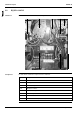
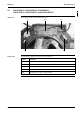
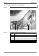
5.4 R(Y)P125L7W1
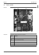
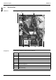
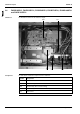
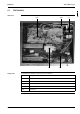
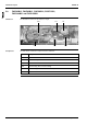
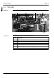
Switch box The illustration below shows the switch box layout.
Components The table below contains the components of the switch box.
F1C
PCB1
C2R
X1M
T1R
PCB2
K1M
C1R
Symbol Component
X1M Terminal strip
PCB1 Printed circuit board
PCB2 Printed circuit board (interlock PCB)
T1R Transformer
C1R Fan motor capacitor 1
C2R Fan motor capacitor 2
K1M Magnetic contactor
F1C Overcurrent relay