
Service manual

Switch Box Layout ESIE03–01
1–78 Part 1 – System Outline
3
1
1
4
5
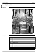
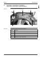
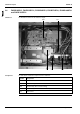
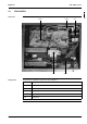
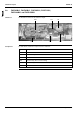
5.2 R(Y)P71-100L7V1
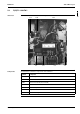
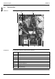
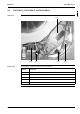
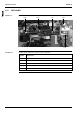
Switch box The illustration below shows the switch box layout.
Components The table below contains the components of the switch box.
-
-
-
-
-
-
-
-
Symbol Component
T1R Transformer
K1S Starting contactor
C1R Fan motor capacitor
K1M Magnetic contactor
F1C Overcurrent relay
X1M Terminal strip
PCB1 Printed circuit board
PCB2 Printed circuit board (interlock PCB)