
Service manual

ESIE03–01 Switch Box Layout
Part 1 – System Outline 1–77
3
4
5
1
Part 1
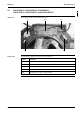
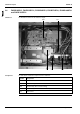
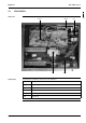
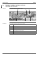
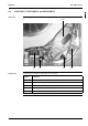
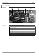
5 Switch Box Layout
5.1 What Is in This Chapter?
Introduction This chapter shows the switch box components.
Outdoor units This chapter contains the following switch box layouts:
Indoor units This chapter contains the following switch box layouts:
Switch box layout See page
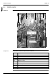
5.2–R(Y)P71-100L7V1 1–78
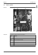
5.3–R(Y)P71~100L7W1 1–79
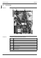
5.4–R(Y)P125L7W1 1–80
Switch box layout See page
5.5–FHYCP35B7V1, FHYCP45B7V1, FHYCP60B7V1, FHYCP71B7V1,
FHYCP100B7V1 and FHYCP125B7V1
1–81
5.6–FHYBP35B7V1, FHYBP45B7V1, FHYBP60B7V1, FHYBP71B7V1,
FHYBP100B7V1 and FHYBP125B7V1
1–82
5.7–FDYP125B7V1 1–83
5.8–FHYP35BV1, FHYP45BV1, FHYP60BV1, FHYP71BV1, FHYP100BV1 and
FHYP125BV1
1–84
5.9–FUYP71BV17, FUYP100BV17 and FUYP125BV17 1–85
5.10–FAYP100BV1 1–86
5.11–FAYP71LV1 1–87
5.12–FHYKP35BV1, FHYKP45BV1, FHYKP60BV1 and FHYKP71BV1 1–88
5.13–FDYMP71~125L7V1 1–89