
Service manual


ESIE03–01 Functional Diagrams
Part 1 – System Outline 1–67
3
1
4
5
Functional
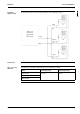
diagram: Triple
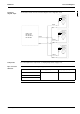
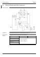
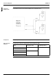
The illustration below shows the functional diagram of the refrigeration circuit.
Components For a description of the components, see ’Piping Components’ on page 1–75.
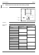
Pipe connection
diameters
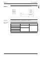
The table below contains the refrigerant pipe connection diameters (O.D.).
Liquid
Gas
Liquid
Gas
Liquid
Gas
Liquid
Gas
Outdoor unit:
RP100L7V1,
RP100L7W1 or
RP125L7W1
14
14
7
R2T
7
R2T
7
R2T
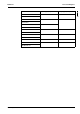
Model ∅ Gas pipe (flare) ∅ Liquid pipe (flare)
RP100L7V1 19.1 mm 9.5 mm
RP100L7W1
RP125L7W1
14