
Service manual

Functional Diagrams ESIE03–01
1–64 Part 1 – System Outline
3
1
1
4
5
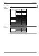
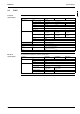
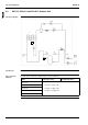
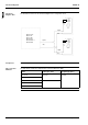
4.2 RP71L7, RP100L7 and RP125L7: Outdoor Unit
Functional diagram The illustration below shows the functional diagram of the refrigeration circuit.
Components For a description of the components, see ’Piping Components’ on page 1–75.
Pipe connection
diameters
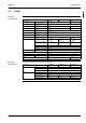
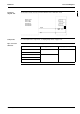
The table below contains the refrigerant pipe connection diameters.
18
11
4
2b
68
10
7
13 12
3
Liquid
piping
Gas
piping
8
R2T
R1T
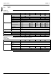
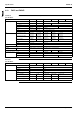
Model ∅ Gas pipe (flare) ∅ Liquid pipe (flare)
RP71L7V1
P For pair, see page 1-65.
P For twin, see page 1-66.
P For triple, see page 1-67.
RP71L7W1
RP100L7V1
RP100L7W1
RP125L7W1