
Service manual

ESIE03–01 Specifications
Part 1 – System Outline 1–51
3
1
4
5
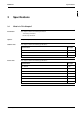
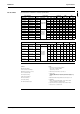
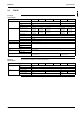
Electrical Data The table below contains the electrical specifications.
Unit combination Power supply Compressor OFM IFM
Indoor unit Outdoor unit Hz-Volts Voltage range MCA TOCA MFA LRA RLA kW FLA kW FLA
FHYCP100 RP100L7V1 50-230
Max.50Hz-264V
Min.50Hz-198V
22.7 34.8 40 97 16.7 0.090 0.8 0.090 1.0
FUYP100 RP100L7V1 50-230 22.4 34.8 40 97 16.5 0.090 0.8 0.090 1.0
FHYP100 RP100L7V1 50-230 22.5 34.5 40 97 16.8 0.090 0.8 0.130 0.7
FAYP100 RP100L7V1 50-230 21.7 34.2 40 97 16.4 0.090 0.8 0.049 0.4
FHYBP100 RP100L7V1 50-230 22.6 34.8 40 97 16.6 0.090 0.8 0.135 1.0
FDYMP100 RP100L7V1 50-230 22.4 34.8 40 97 16.5 0.090 0.8 0.135 1.0
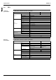
FHYCP100 RP100L7W1 50-400/230
Max.50Hz-
440/253V
Min.50Hz-
360/197V
9.2 11.8 16 47 5.9 0.090 0.8 0.090 1.0
FUYP100 RP100L7W1 50-400/230 9.4 11.8 16 47 6.1 0.090 0.8 0.090 1.0
FHYP100 RP100L7W1 50-400/230 9.3 11.5 16 47 6.2 0.090 0.8 0.130 0.7
FAYP100 RP100L7W1 50-400/230 8.7 11.2 16 47 6.0 0.090 0.8 0.049 0.4
FHYBP100 RP100L7W1 50-400/230 9.3 11.8 16 47 6.0 0.090 0.8 0.135 1.0
FDYMP100 RP100L7W1 50-400/230 9.4 11.8 16 47 6.1 0.090 0.8 0.135 1.0
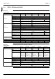
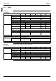
Unit combination Power supply Compressor OFM IFM
Indoor unit Outdoor unit Hz-Volts Voltage range MCA TOCA MFA LRA RLA kW FLA kW FLA
FHYCP125 RP125L7W1 50-400/230
Max.50Hz-
440/253V
Min.50Hz-
360/197V
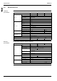
11.6 15.3 20 59 7.4 0.065+
0.085
0.6+
07
0.09 1.0
FUYP125 RP125L7W1 50-400/230 11.6 15.3 20 59 7.4 0.065+
0.085
0.6+
0.7
0.09 1.0
FHYP125 RP125L7W1 50-400/230 11.4 15.0 20 59 7.5 0.065+
0.085
0.6+
0.7
0.13 0.7
FHYBP125 RP125L7W1 50-400/230 12.1 15.7 20 59 7.5 0.065+
0.085
0.6+
0.7
0.225 1.4
FDYMP125 RP125L7W1 50-400/230 12.1 15.7 20 59 7.5 0.065+
0.085
0.6+
0.7
0.225 1.4
FDYP125 RP125L7W1 50-400/230 14.9 18.5 20 59 7.5 0.065+
0.085
0.6+
0.7
0.5 4.2
Symbols:
MCA: Min. Circuit Amps
TOCA: Total Over-current Amps
MFA: Max. Fuse Amps (see note 7)
LRA : Locked Rotor Amps
RLA : Rated Load Amps
OFM : Outdoor Fan Motor
IFM : Indoor Fan Motor
FLA : Full Load Amps
kW : Fan Motor Rated Output
Notes:
1. RLA is based on the following conditions:
Indoor temp.: 27°CDB/19.5°CWB
Outdoor temp. : 35°CDB.
2. TOCA means the total value of each OC set.
3. Voltage range
Units are suitable for use on electrical systems where voltage
supplied to unit terminals is not below or above listed operation range
limits.
4. Maximum allowable voltage unbalance between phases is 2%.
5. MCA/MFA
MCA = 1.25 x RLA + all FLA, MFA = < 2.25 x RLA + all FLA
(next lower standard fuse rating Min. 16A).
6. Select wire size based on the larger value of MCA or TOCA.
7. Instead of fuse, use circuit breaker.