
Service manual


General Outline: Indoor Units ESIE03–01
1–40 Part 1 – System Outline
3
1
1
4
5
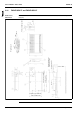
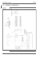
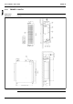
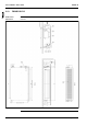
2.17 FHYKP60BV17 and FHYKP71BV17
Outlook and
dimensions
The illustration below shows the outlook, the dimensions and the installation and service space of the
unit (mm).
1000 or more
Hole
Fresh air intake position
Suspension bolt
Front discharge dust
connection postion
Suspension position
Ceiling opening
350 Suspension position
760 Ceiling opening
2
0
0
o
r
m
o
r
e
2
0
0
o
r
m
o
r
e
2
0
0
o
r
m
o
r
e
1
5
0
0
o
r
m
o
r
e
Hole
Required space