
Service manual


ESIE03–01 General Outline: Indoor Units
Part 1 – System Outline 1–25
3
1
4
5
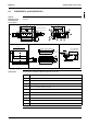
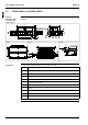
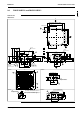
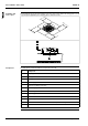
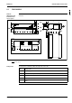
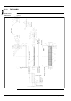
Components The table below contains the different components of the unit.
No. Component
1 Air discharge grille
2 Air suction grille
3Air filter
4 Gas pipe connection
5 Liquid pipe connection
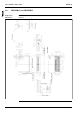
6 Drain pipe connection
7 Grounding terminal (inside the electric components box) M4
8 Suspension bracket
9 Backward piping and wiring connection opening lid
10 Upward piping and wiring connection opening lid
11 Right side pipe connection (slit hole)
12 Left back drain pipe connection (slit hole)
13 Left side drain pipe connection (slit hole)
14 Right side drain pipe connection (slit hole)
15 Wall hole for taking out in piping back (∅ 100 mm)
16 Upward drain pipe connection (∅ 60 mm)
17 Upward gas pipe connection (∅ 36 mm)
18 Upward liquid pipe connection (∅ 26 mm)
— Name plate: In case of a wireless remote controller, this position is a signal receiver.