
Service manual

ESIE03–01 Disassembly and Maintenance: Indoor Units
Part 5 – Disassembly and Maintenance 5–37
3
5
1
5
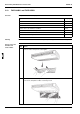
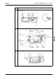
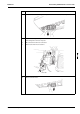
3 Pull down the control box and let it hang by the 2 locations in the rear. Electrical parts can
now be removed.
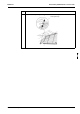
4 Disconnect the connector mounted on the PC board.
5 Remove the PC board installation screw.
Step Action
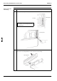
Control box
Rear panel
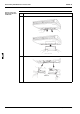
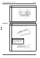
X11A
Primary side of
transformer
X27A
In and outdoor
unit connection
X20A
Fan motor
X29A
Swing motor
X26A
Fan motor
feedback
CN5
Remote
controller
CN10
Secondary side
of transformer
X19A
Suction air
thermistor
X18A
Heat exchanger
thermistor
X14A
for limit switch