
Service manual


ESIE03–01 Disassembly and Maintenance: Indoor Units
Part 5 – Disassembly and Maintenance 5–29
3
5
1
5
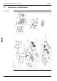
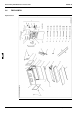
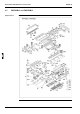
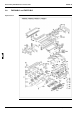
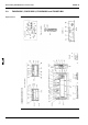
Components The table below contains the components of the exploded view.
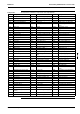
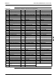
No. Component No. Component No. Component
B1 Evaporator assy E14 Wire harness (swing motor) F10.1 Insulation tube
B1.1 Distributor E15 Wire harness (power unit) F10.2 Vertical vane air discharge
B1.2 Union joint (gas line) E16 Wire harness (power unit) F10.2.1 Set plate vertical vane
B1.3 Union joint (liquid line) E17 Thermistor F10.2.2 Vertical vane air discharge
B1.4 Flare nut E18 Wire clip F10.2.3 Connecting bar vertical
vane
B1.5 Flare nut E19 Clamp F10.3 Cap drain socket
B1.6 Retainer thermistor E20 Lock metal F11 Supporter
C1 Fan assy E21 Wire clip F12 Horizontal vane assy
C1.1 Top plate fan assy E22 Bush thermistor F12.1 Horizontal vane
C1.2 Fan housing E23 Sound absorbing material F12.2 Rod horizontal vane
C1.3 Fan housing E24 Housing power unit F12.3 Rod horizontal vane
C1.4 Fan rotor F1 Top plate assy F12.4 Rod horizontal vane
C1.4.1 Hexagon socket screw F2 Bottom plate assy F13 Decorative plate
C1.5 Fan rotor F2.1 Name plate assy F14 Air suction grille assy
C1.5.1 Hexagon socket screw F2.1.1 Housing signal receiver F14.1 Air suction grille
C1.6 Fan motor F2.1.2 DAIKIN name plate F14.2 Fixture air suction grille
C1.7 Lock metal fan motor F3 Side plate assy (right) F14.3 Hinge air suction grille
C1.8 Motor base F3.1 Side plate (right) F15 Side plate assy
C1.9 Fan shaft F3.2 Swing motor assy F15.1 Cover side plate
C1.10 Coupling fan shaft F3.3 Set plate swing motor F16 Side plate (left)
C1.11 Fan bearing F3.4 Connecting arm horizontal
vane
F17 Blind plate piping hole
C1.12 Bearing holder F3.5 Crank air swing F18 Blind plate piping hole
C1.13 Set plate bearing holder F3.6 Bearing horizontal vane F19 Wire clip
C1.14 Wire clip F3.7 Heat insulation material F20 Set plate drain pan
C2 Air filter F3.8 Heat insulation material F21 Supporter fan
E1 Electric components assy F3.9 Heat insulation material F22 Retainer
E2 Switch box F3.10 Sealer F23 Air guide plate
E3 Cover switch box F3.11 Sealer F24 Heat insulation cover top
plate
E4 Printed circuit (power unit) F3.12 Lock metal F25 Insulation cover piping hole
E5 Printed circuit F3.13 Wire clip F27 Protector heat exchanger
E5.1 Printed circuit (control unit) F4 Side plate assy F28 Heat insulation cover
E5.1.1 Air thermistor F4.1 Side plate (left) F29 Heat insulation cover
E5.1.2 Connector F4.2 Bearing horizontal vane F30 Suspension bolt
E5.2 Capacity control adaptor F4.3 Heat insulation material K1 Drain hose
E6 Plastic case F4.4 Heat insulation material K2 Hose band
E7 Capacitor fan motor F4.5 Heat insulation material K3 Insulation tube (liquid line)
E8 Terminal block F5 Hook metal K4 Insulation tube (gas line)
E9 Terminal block F6 Hook metal K5 Sealer
E10 Wire harness (transmission) F7 Side plate heat exchanger K6 Sealer
E11 Wire harness (remote con-
troller)
F8 Retainer refrigerant piping K7 Operation manual
E12 Wire harness (feed back) F9 Set plate drain pan
E13 Wire harness (fan motor) F10 Drain pan assy