
Service manual

ESIE03–01 Disassembly and Maintenance: Indoor Units
Part 5 – Disassembly and Maintenance 5–19
3
5
1
5
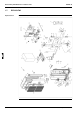
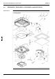
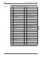
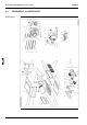
Components The table below contains the components of the exploded view.
No. Component No. Component
B1 Heat exchanger assy E24 Float switch
B1.1 Distributor with filter E25 Fan motor
B1.2 Single union joint F1 Casing assy
B1.3 Single union joint F6 Inspection cover assy
B1.4 Flare nut F8 Drain pan assy
B1.5 Flare nut F8.1 Drain plug
C1 Fan rotor (turbo) F9 Sound absorbing material
C2 Lock washer F10 Heat exchanger blind plate assy
C3 Nut with washer F11 Heat exchanger mounting plate
E1 Switch box assy F12 Hold plate assy
E2 Switch box body F13 Panel mounting plate
E4 Bell mouth F14 Drain pump mounting plate
E5 Switch box cover assy 1 F15 Vibration isolator
E6 Switch box cover 2 F16 Hexagon mounting bolt
E7.1 PCB assy F17 Vibration isolator
E7.1.1 Air thermistor F18 Nut with washer
E9 Capacitor F19 Feeler bulb clamp
E10 Terminal F21 Rubber bush
E11 Terminal block F22 Inner heat insulator
E12 Power supply transformer G1 Drain hose
E13 Wire harness G2 Hose band
E14 Wire harness H1 Top tray assy
E15 Wire harness H2 Bottom tray assy
E16 Wire harness K1 Drain hose assy
E19 Grounding wire K2 Hose band
E20 Grounding screw K3 Insulation for joint (liquid)
E21 Thermistor (liquid) K4 Insulation for joint (gas)
E23 Drain pump K5 Sealing material