
Service manual

ESIE03–01 Disassembly and Maintenance: Outdoor Units
Part 5 – Disassembly and Maintenance 5–15
3
5
1
5
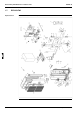
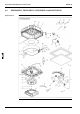
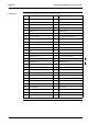
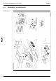
Components The table below contains the components of the exploded view.
No. Component No. Component
1 #7026# Compressor 35 Magnetic switch
2 Sound insulation (for comp/1) 36 Transformer
3 Rubber cushion pre-assy 37 Fan motor capacitor
4 Bolt for compressor 38 Motor operated valve coil
5 Nut with washer 39 Thermistor
6 Plate finned coil heat exch as 40 Thermistor
7 Liquid receiver assy 41 Thermistor
8 Flare nut 3/8 42 Terminal strip
9 Flare nut FNS-6 43 Wire clip
10 Valve cap 44 Compressor cable
11 Stop valve cap 45 Fan propellor
12 Check valve 46 Washer
13 Valve core 47 Top plate assy
14 Shraeder round dustcap 48 Front plate assy
15 Low pressure switch 49 Front plate (2) assy
16 High pressure switch 50 Side plate assy
17 Check valve 51 Part.Plate assy
18 Check valve 52 Fan motor stand
19 Solenoid valve body 53 Fan motor stand (up)
20 T-joint TSS2-2-2 54 Fan motor stand left
21 Liquid stop valve assy 55 Fan motor stand right
22 FI233 Filter 56 Suction grill
23 Strainer 57 Packing case p/m
24 T-joint 58 Coil of 4-way valve
25 Muffler 59 Thermal insulation tube
26 Gas stop valve assy 60 Cover
27 4-way reversing valve body 61 Piping cover (rear)
28 Filter 62 Stop valve mounting plate
29 Motor operated valve body 63 Bell mouth assy
30 Filter 64 Air discharge grill
31 Ele. compo. mounting assy 65 Handle
32 PCB assy 66 Bottom frame assy
33 Resin cover assy 67 Installation leg painted
34 El. compo. box lower cover 68 Bottom tray assy
69 Cushion top 74 Thermistor mounting spring
70 Thermistor fixing plate 75 HPS cable
71 Single phase ac fan motor 76 Solenoid valve coil
72 Single phase ac fan motor 77 Stopper
73 Thermistor mounting spring