
Service manual


General Outline: Indoor Units ESIE03–01
1–16 Part 1 – System Outline
3
1
1
4
5
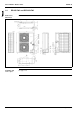
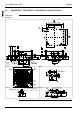
2.3 FHYBP35B7V1 and FHYBP45B7V1
Outlook,
dimensions and
installation and
service space
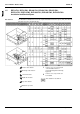
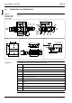
The illustration below shows the outlook, the dimensions and the installation and service space of the
unit (mm).
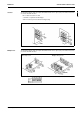
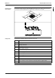
Components The table below contains the different components of the unit.
14 x M5
8
B
C
6 x M5
7
A
5
3
46
14 x M4
101
9
2
150
200
67
98 98 152178
250
650
150
4x150 = 600
600
160 P.C.D.
D125
100
57
700
135
300
60 110
230
50
60
595
25 800
45 46
315
195
2x65 = 130
630
39
750
145
6x65 = 390
630
65
460
150
215
245
3x150 = 450
485
View A View B View C
Knock out hole
Fresh air intake
Suspension
position
300 or more
Suspension bolt
350 or more
No. Component
1 Liquid pipe connection
2 Gas pipe connection
3 Drain pipe connection (O.D. 32 mm, I.D. 25 mm)
4 Remote controller wiring connection
5 Power supply connection
6 Drain hole (O.D. 32 mm, I.D. 25 mm)
7 Air filter
8 Air suction side
9 Air discharge side
10 Name plate