
Service manual

Field settings ESIE03–01
4–22 Part 4 – Commissioning and Test Run
3
1
4
5
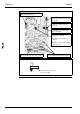
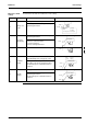
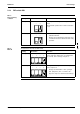
[Nr. 1] The attachment position of a capacity
setting adaptor (CN26/X26A)
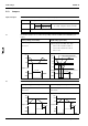
Figure 3: The outline drawing of the PCB assembly (including the resin case)
[Nr. 4] <Only 71, 100 exclude R(Y)P> The
attachment position of a short circuit
connector (CN9/X9A)
[Nr. 5] <Only DAIKIN compressor>
Setting jumper position (JH)
[Nr. 6] <Only 230V> Setting jumper
position (J4)
[Nr. 7] <Only cooling machine> Setting
jumper position (J5)
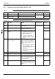
<Terminal board R/S/T>
M5 screw attachment position: Six places
<Terminal board 1/2/3>
M4 screw attachment position: Three places
[Nr. 3] <Only 71, 100> The attachment
position of a short circuit connector
(CN12/X12A)
[Nr. 2] <Only 71, 100> The connector
attachment position for terminal protection
(CN14/X14A)
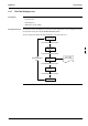
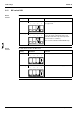
Figure 4: Capacity establish adaptor illustration
J80
For the correct value, refer to
“accessories table”