
Service manual

ESIE03–01 Field settings
Part 4 – Commissioning and Test Run 4–21
3
4
5
1
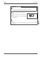
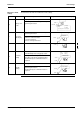
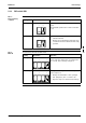
<Is it a C/O or H/P?> H/P
C/O
Please cut jumper J5 as shown in fig. 1 on this page. (Refer to fig. 3 [Nr. 7])
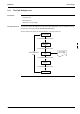
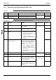
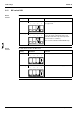
<Replacement of the printed circuit board ass’y>
(CAUTION)
Please replace the PCB ass.y when it is still included in the
resin case.
Please reconnect all connectors as before according to the
electric wiring diagram.
<Test run>
Please confirm that a test run is performed and that the system can operate normally after finishing
the replacement.
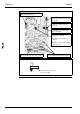
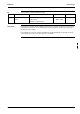
J* * : 4, 5,
H
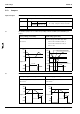
Figure 1
The cut position of a jumper line