
Service manual

Field settings ESIE03–01
4–20 Part 4 – Commissioning and Test Run
3
1
4
5
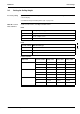
2.10 Field settings when using a spare part PCB of Sky-Air L-series outdoor unit
When In case the outdoor PCB needs to be replaced by a spare part PCB, it is required to execute
below-mentioned field settings to ensure correct operation of the unit.
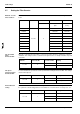
Required action In case of repair using this part, replace the part according to the following instruction:
Attention on service!
1 Please be sure to work after turning off all related circuit breakers.
2 Before starting the work, please touch the metal part of the product to discharge static electricity.
3 Please exchange PCB ass.y when it is still included in the resin case.
(If it would be removed from the resin case, it can cause a PCB failure.)
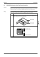
- The parts for replacement : 1 The PCB ass’y
- Accessories: 1 Capacity setting adaptor
2 The screw for terminal board : Two kinds (M4×3 pieces,
M5×6 pieces)
Please replace the printed circuit board according to the following flow chart of “The flow to setup
the printed circuit board ass’y”.
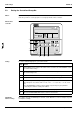
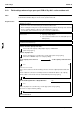
The flow to setup the printed circuit board ass.y
<Please check the capacity of the unit.>
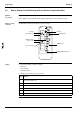
Please attach the capacity setting adaptor (fig. 4) to CN26/X26A.
(Refer to fig. 3 [Nr. 1])
<Please cut jumper JH>
Please cut jumper JH, as shown in fig. 1 on this page. (Refer to fig. 3 [Nr. 5])
(It becomes a DAIKIN compressor setup by cutting.)
<Is the capacity of the unit 71 or
100?>
<Is the capacity of the unit 125?>
Yes Yes
In the case of 71 or 100
Please remove and reuse the two following connectors from the original printed circuit board
ass’y.
- Please attach the connector for terminal protection to CN14/X14A. (Refer to fig. 3 [Nr. 2])
- Please attach a short circuit connector to CN12/X12A. (Refer to fig. 3 [Nr. 3])
<Is the model R(Y)P71L7V1 or R(Y)P100L7V1?> No
Yes
Please cut jumper J4, as shown in fig. 1 on this page. (Refer to fig. 3 [Nr. 6])
(It becomes a setup for 230V by cutting.)
<Is it a C/O or H/P?>
No