
Service manual


General Outline: Indoor Units ESIE03–01
1–14 Part 1 – System Outline
3
1
1
4
5
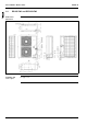
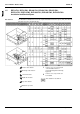
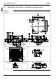
2.2 FHYCP35B7V1, FHYCP45B7V1, FHYCP60B7V1 and FHYCP71B7V1
Outlook and
dimensions
The illustration below shows the outlook and the dimensions of the unit (mm).
4 x M8~M10
12 x M4
A
4 x M4
12 x M4
12 x M4
C
D
10
B
9
6
7
214
58
3
8580
D75
240
200
150
125
110
95
750
160
230
1030
260
315
295
350
20
5584055
295
802x100=20080
150
160
110
95
350
40
5584055
852x100=20080
165
80
60
80
160
110
95
802x100=20080
350
110
95
160
2X100=200
350
40
420
420
950
950
11
12
12
12
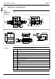
View A View B
View DView C
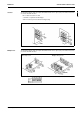
For fresh air intake kit connec-
tion (direct installation type)
Prepared hole
860~890 (Ceiling opening)
680 (Suspension position)
300 or less
Prepared hole
Prepared hole
Adjustable (0~550)
S
uspension bolt
860~890 Ceiling opening
780 Suspension position