
Service manual

ESIE03–01 Troubleshooting
Part 3 – Troubleshooting 3–17
3
3
4
5
1
1.10 Troubleshooting with the Remote Controller: System Malfunctions
Malfunction
overview
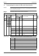
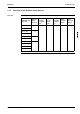
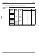
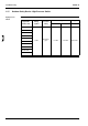
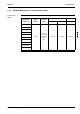
The table below contains an overview of the system malfunctions.
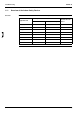
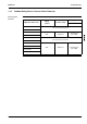
Symbols and notes The table below describes the symbols and notes used in the malfunction overview.
If... Then...
Rem.
contr.
display
Location of the malfunction
Malfunction description See page
Other
than PCB
PCB
outd.
unit
PCB
ind.
unit
Rem.
contr.
U0
———
Gas Shortage Detection (UO) 3–62
U1
——
Reverse Phase (U1) 3–63
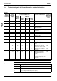
U4
or
UF
{{—
Transmission Error between
Indoor and Outdoor Unit (U4
or UF)
3–65
U5
— {{
Transmission Error between
Indoor Unit and Remote Con-
troller (U5)
3–67
U8
— {{
Transmission Error between
MAIN Remote Controller and
SUB Remote Controller (U8)
3–68
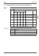
UA
— { —
Malfunctioning Field Setting
Switch (UA)
3–69
Symbol / note Description
High probability of malfunction
{ Low probabiltiy of malfunction
No possibility of malfunction (do not replace)