
Service manual

ESIE03–01 Troubleshooting
Part 3 – Troubleshooting 3–15
3
3
4
5
1
1.8 Troubleshooting with the Indoor Unit LEDs and the Remote Controller
Shutdown For some errors, the system only shuts down when the error occurs several times. This means that
you have to wait until the system shuts down to be able to see the flashing LED on the front panel and
the error code on the remote controller.
Malfunction
overview
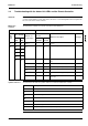
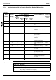
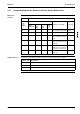
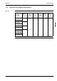
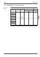
The table below contains an overview of the indoor unit malfunctions.
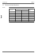
Symbols and notes The table below describes the symbols and notes used in the malfunction overview.
If... Then...
LED
front
panel
Indoor unit LED
Remote con-
troller display
Location of the mal-
function
Malfunction description See page
H1P
(HAP)
H2P
(HBP)
Other
than PCB
PCB
ind. unit
xcc
Note 1 — —
Normal —
ccw
A1
— {
Malfunctioning Indoor PCB (A1) 3–26
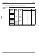
cx
w
—
x
—
cc
A3
—
Malfunctioning Drain Water Level System
(A3)
3–27
A6
Indoor Unit Fan Motor Lock (A6) 3–29
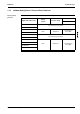
AF
{
Malfunctioning Drain System (AF) 3–31
AJ
{
Malfunctioning Capacity Setting (AJ) 3–32
C4 or C9
Thermistor Abnormality (C4 or C9) 3–34
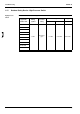
CJ
{
Malfunctioning Remote Controller Air Ther-
mistor (CJ)
3–36
Symbol / note Description
Note 1 Variety of circumstances
w
LED is ON
c
LED is flashing
x
LED is OFF
High probability of malfunction
{ Low probabiltiy of malfunction
No possibility of malfunction (do not replace)