
Service manual

ESIE03–01 Overview of the heating mode functions
Part 2 – Functional Description 2–41
3
2
4
5
1
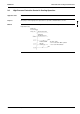
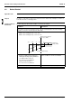
Heating integral
capacity
The integral heating capacity is calculated by using the indoor unit data (R2T - R1T) divided by the
compressor running time.
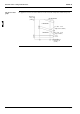
Defrost control
RYP71-125L
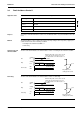
The illustration below shows the defrost control.
Integral
capacity
Compr. ON time
Heating
Defrosting
Diminishing
integral capacity
Max. integral
capacity value
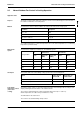
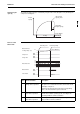
Note Control and time Description
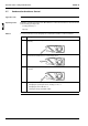
1 Motorized valve control
during defrost operation
After a defrost activation, the defrost motorized valve is at
480 pulses for a certain amount of time, and is then closed
gradually to 100 pulses.
Only when the discharge pipe temperature is high during
defrost, the motorized valve opens at intervals.
2 Motorized valve control
after defrost operation
The motorized valve is controlled to an optimum opening
and the most suitable operating speed, according to the
operating conditions at defrost activation.
3 Outdoor unit fan
after defrost operation
The fan operates at optimum fan tap, according to the oper-
ating conditions at defrost activation.
1
0˚C
480
400
300
200
100
Defrosting start Defrosting ending
Outd. unit heat
exchager temp. (Tc)
Compressor
4-way valve
Motorized valve
Outd. unit fan
Ind. unit fan
ON
OFF
ON
OFF
ON
OFF
ON
OFF
Note 4
Note 3
Note 1
Note 2