
Service manual

ESIE03–01 General Functionality
Part 2 – Functional Description 2–9
3
2
4
5
1
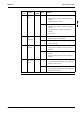
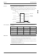
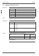
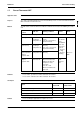
Time chart The time chart below illustrates emergency operation.
P In cooling, the unit runs for 20 min and then stops for 10 min in order to avoid freeze-up of the
indoor coil.
P During emergency operation, do not attempt to operate the equipment from the remote controller.
The remote controller shows 88 while the emergency operation is active on the indoor unit.
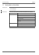
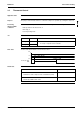
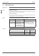
Active components The table below shows when the most important components are active in the different forced
operating modes.
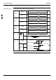
Additional info To avoid misunderstandings, take the following into account:
P If the PCB or the motorized valve is malfunctioning, emergency operation cannot be carried out.
P No signal is transmitted between the indoor and outdoor units and remocon.
P If a safety device should be activated during emergency operation, all actuators are turned OFF.
P “Heat” cannot be set for c/o air conditioners.
P Emergency operation uses (and switches ON) both indoor and outdoor control PCBs. The outdoor
control PCB determines the changeover.
P In heating, defrosting is activated once every hour.
Power supply
Motorized valve
4-way valve
Compressor
Solenoid valve
Fully closed
10 s
Outdoor unit fan
480
Normal control
Heating: ON
Cooling: OFF
60s
Component Forced cooling Forced heating Forced defrosting
Compressor ON ON ON
4-way valve RYP71-125L: OFF RYP71-125L: ON RYP71-125L: OFF
Outdoor unit fan H fan speed H fan speed OFF
Indoor unit fan H fan speed H fan speed H fan speed
Drain pump ON OFF ON