
Service manual

ESIE03–01 PCB Layout
Part 1 – System Outline 1–119
3
1
4
5
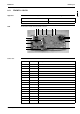
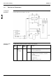
8.9 FAYP100BV1
Applicable The table below contains the applicable PCB number and unit of this PCB type.
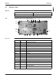
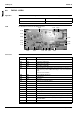
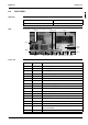
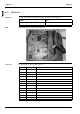
PCB The illustration below shows the PCB connectors.
Connectors The table below describes the PCB connectors.
PCB No. Unit
ECOO64 FAYP100BV1
X5A
X18A
X20A
X11A
X27A
X98A
X10A
X25A X29A X24A X35A X26A X30A X14A X15A
X23A
X19A
X40A
Connector Connected to Description
X5A X1M Terminal strip (P1 and P2)
X10A X2A on A2P Power supply PCB
X11A X1A on A2P Power supply PCB
X14A 33A Limit switch (swing flap)
X15A — Float switch
X18A R2T Heat exchanger thermistor
X19A R1T Air thermistor
X20A M1F Fan motor power supply
X23A — Connector for capacity adaptor
X24A X2A on A3P X24A is connected when the wirelesss remote controller is used
X25A — Drain pump motor
X26A M1F Fan motor feedback cable
X27A X2M Power supply and communication to the outdoor unit
X29A M1A Swing flap motor
X30A — Connector to interface adaptor for Sky Air series (DTA102)
X40A — Connector for EKRORO
X35A X1A (KRP4) Connector to group control adaptor power supply (16 VDC) for
optional PCB KRP4
X98A C1R Capacitor (M1F)