
Service manual

PCB Layout ESIE03–01
1–112 Part 1 – System Outline
3
1
1
4
5
8.2 R(Y)P71~125L7V1 and R(Y)P71~125L7W1
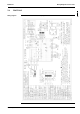
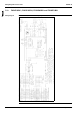
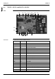
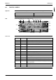
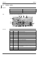
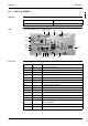
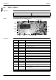
PCB The illustration below shows the PCB connectors.
Connectors The table below describes the PCB connectors.
X14A
X2A
X24A
X40A
X7AX15A
X12A
X9A
X11A
X25A
X8A X27A
X22A
X10A
X26A
X6A
X5A
X4A X1A
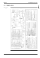
Connector Connected to Description
X2A — ?
X4A R1T Air thermistor
X5A R2T Coil thermistor
X6A R3T Discharge pipe thermistor
X7A-X1A T1R Transformer (220-240V/24,9V)
X8A K1M Magnetic contactor (M1C)
X9A S1PH High-pressure switch
X10A S1PL Low-pressure switch
X11A Q1M Thermo switch (M1F)
X12A Q2M Thermo switch (M2F)
X14A M2F Fan motor 2
X15A M1F Fan motor 1
X22A Y1S 4-way valve
X24A Y1E Electronic expansion valves
X25A E1HC Crankcase heater
X26A — Connector for capacity setting adapter
X27A Y2S Solenoid valve
X40A — Connector for VRV service checker