
Service manual


ESIE03–01 PCB Layout
Part 1 – System Outline 1–111
3
4
5
1
Part 1
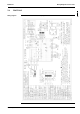
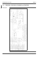
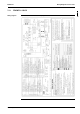
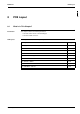
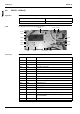
8 PCB Layout
8.1 What Is in This Chapter?
Introduction This chapter contains the following information:
P It describes which unit uses which PCB types
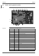
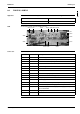
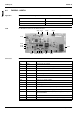
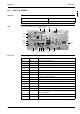
P It shows the PCB connectors.
PCB layouts This chapter contains the following PCB layouts:
PCB layout See page
8.2–R(Y)P71~125L7V1 and R(Y)P71~125L7W1 1–112
8.3–FHYCP35~125B7V1 1–113
8.4–FHYBP35~125B7V1 1–114
8.5–FDYP125~250B7V1 1–115
8.6–FUYP71~125BV1(7) 1–116
8.7–FHYKP35~71BV1 1–117
8.8–FHYP35~125BV1 1–118
8.9–FAYP100BV1 1–119
8.11–FDYMP71~125L7V1 1–121