Service manual
Manuals
Brands
Daikin Manuals
Air Conditioner
FHYP35BV1
101
102
103
104
105
106
107
108
109
110
ESIE03–01
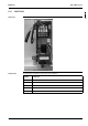
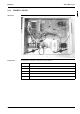
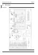
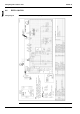
Switch Box
Layout
Part 1 – System Outline
1–89
3
1
4
5
5.13
FDY
MP71~125L7
V1
Switch box
The il
lustra
tion belo
w shows
the swi
tch box l
ayout.
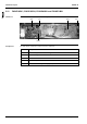
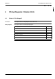
Component
s
The table
below contai
ns the co
mponents
of the sw
itch bo
x.
Symbol
Component
1
...
...
101
102
103
104
105
...
...
390