
Installation manual

24 English
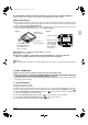
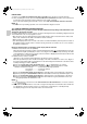
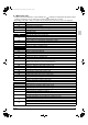
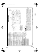
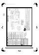
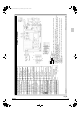
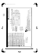
12. WIRING DIAGRAM
(Refer to Fig. 34.35.36.37.38)
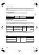
LC Transmission malfunction between the outdoor control units’ inverters (outdoor)
P1 Open-phase or main circuit low voltage (outdoor)
P3 PC-board temperature sensor malfunction (outdoor)
P4 Heat-radiating fin temperature sensor malfunction (outdoor)
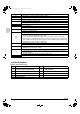
PJ
Type set improper (outdoor unit)
Capacity data is wrongly proset. Or there is nothing programmed in the data hold IC.
U0 Suction pipe temperature abnormal or refrigerant shortage
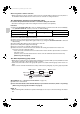
U1
Reverse phase
Reverse two of the L1,L2and L3 leads.
U2
Power source voltage malfunction
Includes the defect in 52C.
U4
UF
Transmission error (indoor unit – outdoor unit)
Incorrect wiring between indoor and outdoor units or malfunction of the PC board
mounted on the indoor and the outdoor units.
If UF is shown, the wiring between the indoor and outdoor units is not properly
wired. Therefore, immediately disconnect the power supply and correct the wiring.
(The compressor and the fan mounted on the outdoor unit may start operation inde-
pendent of the remote controller operation.)
U5
Transmission error (indoor unit – outdoor unit)
Transmission is improper between the indoor unit and the remote controller.
U8
Malfunction in transmission between main and sub remote controls.
(Malfunction in sub remote control.)
UA
Miss setting for multi system
Setting is wrong for selector switch of multi-system. (see switch SS2 on the main
unit’s PC board)
Incorrect combination with indoor unit and outdoor unit
UC Central control address overlapping
1 TO OUTDOOR UNIT 2 NOTE) 6
3 WIRED REMOTE CONTROLLER 4
IN CASE OF SIMULTANEOUS OPERA-
TION SYSTEM
5 INDOOR UNIT (MASTER) 6 INDOOR UNIT (SLAVE)
7 RECEIVER/DISPLAY UNIT 8 REMOTO CONTROLLER
9 NOTE) 7 10 NOTE) 4
11 CONTROL BOX
01_EN_3PN06588-3H.fm Page 24 Monday, April 6, 2009 7:52 PM