00_CV_3PN06588-3H.
FHY35BJV1, FHY45BJV1, FHY60BJV1, FHY71BJV1, FHY100BJV1, FHY125BJV1, FH35BJV1, FH45BJV1, FH60BJV1 EN60335-2-40, FVQ71BV1B, FVQ100BV1B, FVQ125BV1B FAQ71BUV1B, FAQ100BUV1B, FAQ71BVV1B, FAQ100BVV1B Low Voltage 2006/95/EC Machinery Safety 98/37/EC Electromagnetic Compatibility 2004/108/EC Shinri Sada Manager Quality Control Department 1st of April 2009 FUQ71BUV1B, FUQ100BUV1B, FUQ125BUV1B, FUQ71BVV1B, FUQ100BVV1B, FUQ125BVV1B FHQ35BVV1B, FHQ50BVV1B, FHQ60BVV1B, FHQ71BVV1B, FHQ100BVV1B, FHQ125BVV1B (III)
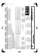
01_EN_3PN06588-3H.fm Page 1 Monday, April 6, 2009 7:52 PM FH(Y)35BJV1 FH(Y)45BJV1 FH(Y)60BJV1 FHY71BJV1 FHY100BJV1 FHY125BJV1 FHYP35BV1 FHYP45BV1 FHYP60BV1 FHYP71BV1 FHYP100BV1 FHYP125BV1 FH35BZV1 FH45BZV1 FH60BZV1 FHQ35BUV1B FHQ50BUV1B FHQ60BUV1B FHQ71BUV1B FHQ100BUV1B FHQ125BUV1B FHQ35BVV1B FHQ50BVV1B FHQ60BVV1B FHQ71BVV1B FHQ100BVV1B FHQ125BVV1B SPLIT SYSTEM Air Conditioner Installation manual CONTENTS 1. SAFETY PRECAUTIONS...........................................................................
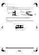
01_EN_3PN06588-3H.fm Page 2 Monday, April 6, 2009 7:52 PM • Install the air conditioner on a foundation strong enough to withstand the weight of the unit. A foundation of insufficient strength may result in the equipment falling and causing injury. • Carry out the specified installation work after taking into account strong winds, typhoons or earthquakes. Failure to do so during installation work may result in the unit falling and causing accidents.
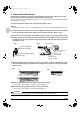
01_EN_3PN06588-3H.fm Page 3 Monday, April 6, 2009 7:52 PM 2. BEFORE INSTALLATION • When moving the unit while removing it from the carton box, be sure to lift it by holding on to the four lifting lugs without exerting any pressure on other parts, especially swing flap, the refrigerant piping, drain piping, and other resin parts. • Be sure to check the type of refrigerant to be used before installing the unit. (Using an incorrect refrigerant will prevent normal operation of the unit.
01_EN_3PN06588-3H.fm Page 4 Monday, April 6, 2009 7:52 PM NOTE • If you wish to use a remote controller that is not listed in “Table 1” on page 3, select a suitable remote controller after consulting catalogs and technical materials. FOR THE FOLLOWING ITEMS, TAKE SPECIAL CARE DURING CONSTRUCTION AND CHECK AFTER INSTALLATION IS FINISHED. a.
01_EN_3PN06588-3H.fm Page 5 Monday, April 6, 2009 7:52 PM 3. SELECTING INSTALLATION SITE ∗≥30 ∗≥30 Air outlet Required service space Air inlet Obstruction Floor ≥300 (1) Select an installation site where the following conditions are fulfilled and that meets your customer’s approval. • Where optimum air distribution can be ensured. • Where nothing blocks air passage. • Where condensate can be properly drained. • Where the ceiling is strong enough to bear the indoor unit weight.
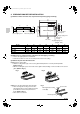
01_EN_3PN06588-3H.fm Page 6 Monday, April 6, 2009 7:52 PM 4. PREPARATIONS BEFORE INSTALLATION (1) Relation of holes for indoor unit, suspension bolt position, piping and wiring.
01_EN_3PN06588-3H.fm Page 7 Monday, April 6, 2009 7:52 PM (3-3)Remove the hanger brackets. • Loosen the 2 bolts (M8) used to attach the hanger brackets which are on each side (4 places left and right) to within 10 mm. (Refer to Fig. 4. 5) • After removing the securing screws (M5) for the hanger brackets which are on the rear side, pull the hanger brackets back (in the direction of the arrow), and remove them. (Refer to Fig. 5) Fig. 4 Fig.
01_EN_3PN06588-3H.fm Page 8 Monday, April 6, 2009 7:52 PM 5. INDOOR UNIT INSTALLATION It may be easier to attach accessory parts before installing the indoor unit. Therefore, please also read the instruction manuals which are provided with the accessory parts. As for the parts to be used for installation work, be sure to use the provided accessories and specified parts designated by our company. (1) Secure the hanger brackets to the suspension bolts. (Refer to Fig.
01_EN_3PN06588-3H.fm Page 9 Monday, April 6, 2009 7:52 PM 6. REFRIGERANT PIPING WORK 〈For refrigerant piping of outdoor units, see the installation manual attached to the outdoor unit.〉 〈Execute heat insulation work completely on both sides of the gas piping and the liquid piping. Otherwise, a water leakage can result sometimes.〉 (When using a heat pump, the temperature of the gas piping can reach up to approximately 120°C, so use insulation which is sufficiently resistant.
01_EN_3PN06588-3H.fm Page 10 Monday, April 6, 2009 7:52 PM Not recommendable but in case of emergency You must use a torque wrench but if you are obliged to install the unit without a torque wrench, you may follow the installation method mentioned below. After the work is finished, make sure to check that there is no gas leak. When you keep on tightening the flare nut with a spanner, there is a point where the tightening torque suddenly increases.
01_EN_3PN06588-3H.fm Page 11 Monday, April 6, 2009 7:52 PM • Make absolutely sure to execute heat insulation works on the pipe-connecting section after checking gas leakage by thoroughly studying the following figure and using the attached heat insulating materials for fitting (6) and (7). (Fasten both ends with the clamps (4).) (Refer to Fig. 13) • Wrap the sealing pad (9) only around the insulation for the joints on the gas piping side. (Refer to Fig.
01_EN_3PN06588-3H.fm Page 12 Monday, April 6, 2009 7:52 PM (1) For piping facing back. • Remove the rear penetration lid and set the piping. (Refer to Fig. 14.16) (2) For piping facing up. • When setting the piping to face up, the L-shaped branch piping kit sold separately is required. • Removing the top penetration lid and use the L-shaped branch piping kit sold separately to set the piping. (Refer to Fig. 14.15) (3) For piping facing right.
01_EN_3PN06588-3H.fm Page 13 Monday, April 6, 2009 7:52 PM 7. DRAIN PIPING WORK (1) Carry out the drain piping. • Make sure piping provides proper drainage. • You can select whether to bring the drain piping our from the rear right, right, rear left, or left. For rear rightfacing and right-facing situations, refer to “6. REFRIGERANT PIPING WORK” on page 9 for rear left-facing and left-facing situations. (Refer to Fig. 18) Fig.
01_EN_3PN06588-3H.fm Page 14 Monday, April 6, 2009 7:52 PM Fig. 20 Fig. 22 Clamp (2) (attached) Drain hose (1) (attached) Taping area (Gray) Clamp (2) (attached) Wrong Fig. 21 Sealing pad (8) (attached) ≤4 ≤4 Sealing pad (8) (attached) Clamp (2) (attached) (Length : mm) < Facing rear right or right > < Facing rear left or left > • Insulate the clamp bracket and drain hose from the bottom using the included sealing pad (8). (Refer to Fig.
01_EN_3PN06588-3H.fm Page 15 Monday, April 6, 2009 7:52 PM 8. WIRING EXAMPLE For the wiring of outdoor units, refer to the installation manual attached to the outdoor units. Confirm the system type. • Pair or Multi system: 1 remote controller controls 1 indoor unit. (standard system) (Refer to Fig. 23) • Simultaneous operation system: 1 remote controller controls 2 indoor units. (2 indoor units operates equally) (Refer to Fig. 24) • Group control: 1 remote controller controls up to 16 indoor units.
01_EN_3PN06588-3H.fm Page 16 Monday, April 6, 2009 7:52 PM NOTE 1. All transmission wiring except for the remote controller wires is polarized and must match the terminal symbol. 2. In case of group control, perform the remote controller wiring to the master unit when connecting to the simultaneous operation system. (wiring to the slave unit is unnecessary) 3.
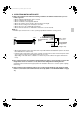
01_EN_3PN06588-3H.fm Page 17 Monday, April 6, 2009 7:52 PM Connection of wiring between units and for the remote control cord (Refer to Fig. 27) • Wiring between units Holding the control box lid, loosen the two securing screws, remove the control box lid, match up the phases on the power source terminal block inside (3P), and make the connections. After this is done, use the attached clamp (4) to bind wiring between units to the anchor point. (Refer to Fig.
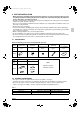
01_EN_3PN06588-3H.fm Page 18 Monday, April 6, 2009 7:52 PM Observe the notes mentioned below when wiring to the terminals. Tightening torque for the terminal screws. • Use the correct screwdriver for tightening the terminal screws. If the blade of screwdriver is too small, the head of the screw might be damaged, and the screw will not be properly tightened. • If the terminal screws are tightened too hard, screws might be damaged. • Refer to the table below for the tightening torque of the terminal screws.
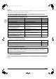
01_EN_3PN06588-3H.fm Page 19 Monday, April 6, 2009 7:52 PM 10. FIELD SETTINGS (1) Make sure the control box lids are closed on the indoor and outdoor units. (2) Field settings must be made from the remote controller and in accordance with installation conditions. • Settings can be made by changing the “Mode No.”, “FIRST CODE NO.” and “SECOND CODE NO.”. • The “Field Settings” included with the remote control lists the order of the settings and method of operation.
01_EN_3PN06588-3H.fm Page 20 Monday, April 6, 2009 7:52 PM When using wireless remote controllers • When using wireless remote controllers, wireless remote controller address setting is necessary. Refer to the installation manual attached to the wireless remote controller for setting instructions. 10-5 Simultaneous operation system individual setting It is easier if the optional remote controller is used when setting the slave unit.
01_EN_3PN06588-3H.fm Page 21 Monday, April 6, 2009 7:52 PM 10-7 Two remote controllers control (Controlling 1 indoor unit by 2 remote controllers) • When using 2 remote controllers, one must be set to “MAIN” and the other to “SUB”. MAIN/SUB CHANGEOVER (1) Insert a screwdriver into the recess between the upper and lower part of remote controller and, working from the 2 positions, pry off the upper part. (The remote controller PC board is attached to the upper part of remote controller.) (Refer to Fig.
01_EN_3PN06588-3H.fm Page 22 Monday, April 6, 2009 7:52 PM PRECAUTIONS 1. Refer to “11-2 HOW TO DIAGNOSE FOR MALFUNCTION” if the unit does not operate properly. 2. After completing the test run, press the INSPECTION/TEST OPERATION run button once to put the unit in inspection mode, and make sure the malfunction code is “00”. (=normal) If the code reads anything other than “00”, refer to “11-2 HOW TO DIAGNOSE FOR MALFUNCTION”.
01_EN_3PN06588-3H.fm Page 23 Monday, April 6, 2009 7:52 PM 11-3 Malfunciton code • For places where the malfunction code is left blank, the “ ” indication is not displayed. Though the system continues operating, be sure to inspect the system and make repairs as necessary. • Depending on the type of indoor or outdoor unit, the malfunction code may or may not be displayed.
01_EN_3PN06588-3H.fm Page 24 Monday, April 6, 2009 7:52 PM LC P1 P3 P4 PJ U0 U1 U2 U4 UF U5 U8 UA UC Transmission malfunction between the outdoor control units’ inverters (outdoor) Open-phase or main circuit low voltage (outdoor) PC-board temperature sensor malfunction (outdoor) Heat-radiating fin temperature sensor malfunction (outdoor) Type set improper (outdoor unit) Capacity data is wrongly proset. Or there is nothing programmed in the data hold IC.
English (ON-RED) LIGHT EMITTING DIODE PRINTED CIRCUIT BOARD A2P (FILTER SIGN-RED) LIGHT EMITTING DIODE FUSE (250V,5A) LIGHT EMITTING DIODE F1U HAP MAGNETIC RELAY (M1A) MAGNETIC RELAY RyA RyC TERMINAL STRIP CURRENT DETECT CIRCUIT PHASE CONTROL CIRCUIT CD PC SELECTOR SWITCH (MAIN/SUB) SS1 PRINTED CIRCUIT BOARD PUSH BUTTON (ON/OFF) A4P BS 3D027501-1 PRINTED CIRCUIT BOARD A3P (RECEIVER/DISPLAY UNIT) WIRELESS REMOTE CONTROLLER THERMISTOR (AIR) R1T WIRED REMOTE CONTROLLER TERMINAL S
26 LIGHT EMITTING DIODE (SERVICE MONITOR GREEN) H3P THERMO SWITCH Q1F MAGNETIC RELAY (M1A) MAGNETIC RELAY (M1P) SELECTOR SWITCH RyA RyP SS1 TERMINAL STRIP PHASE CONTROL CIRCUIT SIGNAL RECEIVER CIRCUIT SIGNAL TRANSMISSION CIRCUIT X2M PC RC TC SELECTOR SWITCH (MAIN/SUB) SS1 PRINTED CIRCUIT BOARD PUSH BUTTON (ON/OFF) A4P BS 3D027502-1 PRINTED CIRCUIT BOARD A3P WIRELESS REMOTE CONTROLLER (RECEIVER/DISPLAY UNIT) THERMISTOR (AIR) R1T WIRED REMOTE CONTROLLER TERMINAL STRIP X1M (220
English (TIMER-GREEN) LIGHT EMITTING DIODE LIGHT EMITTING DIODE (SERVICE MONITOR GREEN) HAP SELECTOR SWITCH (M1F EMBEDDED) MAGNETIC RELAY (M1A) MAGNETIC RELAY (M1P) SELECTOR SWITCH RyA RyP SS1 (INTERFACE ADAPTOR FOR SKY AIR SERIES) TERMINAL STRIP TERMINAL STRIP X2M SIGNAL TRANSMISSION CIRCUIT X35A CONNECTOR TC SELECTOR SWITCH (MAIN/SUB) SS1 PRINTED CIRCUIT BOARD PUSH BUTTON (ON/OFF) A4P BS 3D027503-1 PRINTED CIRCUIT BOARD A3P (RECEIVER/DISPLAY UNIT) WIRELESS REMOTE CONTROLLER TH
28 CAPACITOR (M1F) FUSE (F5A 250V) LIGHT EMITTING DIODE C1 F1U HAP MAGNETIC RELAY (M1P) MOTOR (INDOOR FAN) MOTOR (SWING FLAP) KPR M1F M1S THERMISTOR (COIL-1) THERMISTOR (COIL-2) LIMIT SWITCH (SWING FLAP) TRANSFORMER (220-240V/22V) R2T R3T S1Q T1R SIGNAL TRANSMISSION CIRCUIT SELECTOR SWITCH (MAIN/SUB) SS1 PRINTED CIRCUIT BOARD A4P 3D037842-1D PRINTED CIRCUIT BOARD A3P (RECEIVER/DISPLAY UNIT) 11 (WIRELESS ADDRESS SET) SELECTOR SWITCH (MAIN/SUB) SELECTOR SWITCH (DEFROST-ORANG
English SIGNAL TRANSMISSION CIRCUIT TC SELECTOR SWITCH (MAIN/SUB) SS1 PRINTED CIRCUIT BOARD A3P 3D043825-1B PRINTED CIRCUIT BOARD A2P (RECEIVER/DISPLAY UNIT) SELECTOR SWITCH (WIRELESS ADDRESS SET) X35A CONNECTOR X33A (INTERFACE ADAPTOR X61A 11 FOR SKY AIR SERIES) CONNECTOR X60A (ON/OFF INPUT FROM OUTSIDE) CONNECTOR (GROUP CONTROL ADAPTOR) CONNECTOR (ADAPTOR FOR WIRING) CONNECTOR(DRAIN PUMP) X25A (FLOAT SWITCH) CONNECTOR CONNECTOR FOR OPTIONAL PARTS X15A WIRELESS REMOTE CONTRO
00_CV_3PN06588-3H.