
Installation manual


English 16
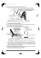
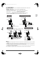
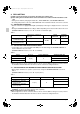
8-2 WIRING EXAMPLE
For the wiring of outdoor units, refer to the installation manual attached to the outdoor units.
Confirm the system type.
• Pair type: 1 remote controller controls 1 indoor unit (standard system).
• Simultaneous operation system: 1 remote controller controls 2 indoor units
(2 indoor units operates equally.)
• Group control: 1 remote controller controls up to 16 indoor units
(All indoor units operate according to the remote controller).
• 2 remote controllers control: 2 remote controllers control 1 indoor unit.
NOTE
1. All transmission wiring except for the remote controller wires is polarized and must match the terminal
symbol.
2. In case of group control, perform the remote controller wiring to the master unit when connecting to the
simultaneous operation system. (wiring to the slave unit is unnecessary)
3. For group control remote controller, choose the remote controller that suits the indoor unit which has the
most functions (as attached swing flap).
4. For simultaneous operation system, connect the remote controller cord to the master unit.
123
P1 P2
123
P1 P2
Main power supply
Main switch
Fuse
Outdoor unit
Indoor unit
Remote
controller
(Optional accessories)
Pair type
123
P1 P2
123
P1 P2
123
P1 P2
Main power supply
Main switch
Fuse
Outdoor unit
Indoor unit(Master)
Indoor unit(Slave)
Remote
controller
(Optional accessories)
Simultaneous operation system
P1 P2
123
123
123
123
123
123
P1 P2 P1 P2 P1 P2
Main power supply Main power supply Main power supply
Main switchMain switchMain switch
FuseFuse Fuse
Outdoor unit
Indoor unit
(Master)
Outdoor unit
Indoor unit
Outdoor unit
Indoor unit
Group control remote controller
(Optional accessories)
Group control
P1 P2
P1 P2 P1 P2
123
123
Main power supply
Main switch
Fuse
Outdoor unit
Indoor unit
Remote
controller
(Optional
accessories)
Remote
controller
(Optional
accessories)
2 remote controllers control
01_EN_3P083811-3T.fm Page 16 Friday, September 3, 2004 10:17 AM