00_CV_3P083811-3U.fm Page 1 Tuesday, November 30, 2004 4:30 PM INSTALLATION MANUAL English SPLIT SYSTEM Air Conditioners Deutsch MODELS (Wall mounted type) FAY71LVE Français FAYP71LV1 FAQ71BUV1B Español Italiano READ THESE INSTRUCTIONS CAREFULLY BEFORE INSTALLATION. KEEP THIS MANUAL IN A HANDY PLACE FOR FUTURE REFERENCE. LESEN SIE DIESE ANWEISUNGEN VOR DER INSTALLATION SORGFÄLTIG DURCH. BEWAHREN SIE DIESE ANLEITUNG FÜR SPÄTERE BEZUGNAHME GRIFFBEREIT AUF.
3P108864-1.fm Page 1 Monday, February 3, 2003 10:23 AM CE - DECLARATION OF CONFORMITY CE - KONFORMITÄTSERKLÄRUNG CE - DECLARATION DE CONFORMITE CE - CONFORMITEITSVERKLARING CE - DECLARACION DE CONFORMIDAD CE - DICHIARAZIONE DI CONFORMITA’ CE - ÄΗΛÙΣΗ ΣΥΜΜΟΡΦÙΣΗΣ CE - DECLARAÇÃO DE CONFORMIDADE CE - OPFYLDELSESERKLÆRING CE - FÖRSÄKRAN OM ÖVERENSTÄMMELSE CE - ERKLÆRING OM SAMSVAR CE - ILMOITUS YHDENMUKAISUUDESTA DAIKIN INDUSTRIES, LTD.
P104327-1B.fm Page 1 Wednesday, November 19, 2003 8:19 PM CE - DECLARATION OF CONFORMITY CE - KONFORMITÄTSERKLÄRUNG CE - DECLARATION DE CONFORMITE CE - CONFORMITEITSVERKLARING CE - DECLARACION DE CONFORMIDAD CE - DICHIARAZIONE DI CONFORMITA’ CE - ÄΗΛÙΣΗ ΣΥΜΜΟΡΦÙΣΗΣ CE - DECLARAÇÃO DE CONFORMIDADE CE - OPFYLDELSESERKLÆRING CE - FÖRSÄKRAN OM ÖVERENSTÄMMELSE CE - ERKLÆRING OM SAMSVAR CE - ILMOITUS YHDENMUKAISUUDESTA DAIKIN INDUSTRIES, LTD.
01_EN_3P083811-3T.fm Page 1 Friday, September 3, 2004 10:17 AM FAY71LVE FAYP71LV1 FAQ71BUV1B SPLIT SYSTEM Air Conditioner Installation manual CONTENTS 1. SAFETY CONSIDERATIONS .............................................................................. 1 2. BEFORE INSTALLATION .................................................................................... 2 3. SELECTING INSTALLATION SITE ..................................................................... 4 4. INDOOR UNIT INSTALLATION ........
01_EN_3P083811-3T.fm Page 2 Friday, September 3, 2004 10:17 AM • When wiring the power supply and connecting the wiring between the indoor and outdoor units, position the wires so that the control box lid can be securely fastened. Improper positioning of the control box lid may result in electric shocks, fire or the terminals overheating. • If the refrigerant gas leaks during installation, ventilate the area immediately. Toxic gas may be produced if the refrigerant gas comes into contact with fire.
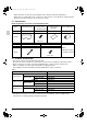
01_EN_3P083811-3T.fm Page 3 Friday, September 3, 2004 10:17 AM • Where machines can generate electromagnetic waves. (Control system may malfunction.) • Where the air contains high levels of salt such as that near the ocean and where voltage fluctuates greatly such as that in factories. Also in vehicles or vessels. 2-2 ACCESSORIES Check the following accessories are included with the unit. Name (1) Installation panel Quantity 1 set (2) Attachment screws for the installation panel 9 pcs.
01_EN_3P083811-3T.fm Page 4 Friday, September 3, 2004 10:17 AM FOR THE FOLLOWING ITEMS, TAKE SPECIAL CARE DURING CONSTRUCTION AND CHECK AFTER INSTALLATION IS FINISHED. 1.
01_EN_3P083811-3T.fm Page 5 Friday, September 3, 2004 10:17 AM • Where pipe between indoor and outdoor units is possible within the allowable limit. (Refer to the installation manual of the outdoor unit.) • Install the indoor and outdoor units, power cable and transmission wiring, at least 1 m from TVs and radios, to prevent distorted pictures and static. (Depending on the type and source of the electrical waves, static may be heard even when more than 1 m away.) • Install the indoor unit no less than 2.
01_EN_3P083811-3T.fm Page 6 Friday, September 3, 2004 10:17 AM (2) Attach to the wall. (a) Check the place for the hole using the included paper pattern for installation (3). • Choose a place so that there is at least a 90 mm gap between the ceiling and the main unit. (b) Temporarily attach the installation panel (1) at the temporary-securing position on the paper pattern for installation (3) and use a level to make sure the drain hose is either level or tilted slightly downward.
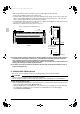
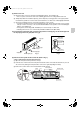
01_EN_3P083811-3T.fm Page 7 Friday, September 3, 2004 10:17 AM (5) Point the pipe in the direction it will be passed out. Insulating tape (4) For right, bottom-right, and back-right piping (Refer to Fig. 6) • Wrap the drain hose and the refrigerant piping together with the insulating tape (4) so that the drain hose is below the refrigerant piping. Refrigerant piping For left, bottom-left, and left-back piping • Remove the front grill. (Refer to Fig. 7) Fig.
01_EN_3P083811-3T.fm Page 8 Friday, September 3, 2004 10:17 AM (6) Hook the indoor unit onto the installation panel. (Refer to Fig. 9) • Placing buffering material between the wall and the indoor unit at this time will make work easier. Service lid Front panel Hook the indoor unit hook onto the installation panel (1). Front grill Place buffering material Wall Be sure to pass all wires through the wiring guide. Refrigerant pipe Wiring (locally procured) Tab (There are 2 places.
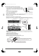
01_EN_3P083811-3T.fm Page 9 Friday, September 3, 2004 10:17 AM • Make sure wiring the units, ground wiring and remote controller wiring are not caught inside the indoor unit. ■ When screwing in the indoor unit Installation panel (accessory) (1) • Remove the front grill. (Refer to Fig. 7) • Secure the indoor unit to the installation panel (1) with the securing screws (6). (Refer to Fig. 11) Refrigerant piping Insulating tape (accessory) (4) M4 × 12L (accessory) (6) Fig. 11 5.
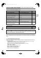
01_EN_3P083811-3T.fm Page 10 Friday, September 3, 2004 10:17 AM Table 2 Flare dimensions A (mm) R22, R407C R410A FAQ-BUV1B 14.2-17.2 N • m (144-175kgf • cm) 8.6 – 9.0 8.7 – 9.1 φ9.5(3/8”) 32.7-39.9 N • m (333-407kgf • cm) 12.6 – 13.0 12.8 – 13.2 φ12.7(1/2”) 49.5-60.3 N • m (505-615kgf • cm) 15.8 – 16.2 16.2 – 16.6 φ15.9(5/8”) 61.8-75.4 N • m (630-769kgf • cm) 19.0 – 19.4 19.3 – 19.7 φ19.1(3/4”) 97.2-118.8 N • m (991-1211kgf • cm) 23.3 – 23.7 R0.4-0.8 A 0 90 Ⳳ0.5 0 0 φ6.
01_EN_3P083811-3T.fm Page 11 Friday, September 3, 2004 10:17 AM CAUTION Be sure to insulate any field piping all the way to the piping connection inside the unit. Any exposed piping may cause condensation or burns if touched. • After checking for gas leaks, be sure to insulate the pipe connections using the supplementary piping insulation tubing and insulating tape (4). The insulating tape (4) should be wrapped from the L-shaped bend all the way to the end inside the unit. (Refer to Fig.
01_EN_3P083811-3T.fm Page 12 Friday, September 3, 2004 10:17 AM • When directly connecting a hard vinyl chloride pipe joint (nominal diameter 13mm) to the drain hose connected to the indoor unit (i.e. for embedded piping, etc.), use a commercially available hard vinyl chloride pipe joint (nominal diameter 13mm). (Refer to Fig. 18) Drain hose connected to the indoor unit Commercially available hard vinyl chloride pipe joint (nominal diameter 13mm) (2) Make sure the drain works properly.
01_EN_3P083811-3T.fm Page 13 Friday, September 3, 2004 10:17 AM 7-2 SPECIFICATIONS FOR FIELD WIRE The remote controller cord should be procured locally. Refer to the Table 4 when preparing one. Table 4 Wire Wiring between units Remote controller cord H05VV-U4G (NOTE 1) Vinyl cord with sheath or cable (2 wire) (NOTE 2) 2 Size (mm ) Length 2.5 – 0.75 - 1.25 Max. 500m NOTE 1. Shows only in case of protected pipes. Use H07RN-F in case of no protection. 2.
01_EN_3P083811-3T.fm Page 14 Friday, September 3, 2004 10:17 AM 8. HOW TO CONNECT WIRINGS AND WIRING EXAMPLE 8-1 HOW TO CONNECT WIRINGS Methods of wiring units and connecting remote controller wiring • Wiring between units Unscrew and remove the service lid. Connect the wiring between units of matching number to the power supply terminal block (4P). And connect the ground wiring to the ground terminal.
01_EN_3P083811-3T.fm Page 15 Friday, September 3, 2004 10:17 AM CAUTION Be sure to attach the sealing material and putty (field supplied) to hole of wiring to prevent the infiltration of water as well as any insects and other small creatures from outside. Otherwise a short-circuit may occur inside the control box. When clamping the wires, be sure no pressure is applied to the wire connections by using the included clamping material to make appropriate clamps.
01_EN_3P083811-3T.fm Page 16 Friday, September 3, 2004 10:17 AM 8-2 WIRING EXAMPLE For the wiring of outdoor units, refer to the installation manual attached to the outdoor units. Confirm the system type. • Pair type: 1 remote controller controls 1 indoor unit (standard system). • Simultaneous operation system: 1 remote controller controls 2 indoor units (2 indoor units operates equally.
01_EN_3P083811-3T.fm Page 17 Friday, September 3, 2004 10:17 AM 9. FIELD SETTING (1) Make sure the service lids are closed on the indoor and outdoor units. (2) Field setting must be made from the remote controller in accordance with the installation condition. • Setting can be made by changing the “Mode No.”, “FIRST CODE NO.”, and “SECOND CODE NO.”. • For setting and operation, refer to the “FIELD SETTING” in the installation manual of the remote controller.
01_EN_3P083811-3T.fm Page 18 Friday, September 3, 2004 10:17 AM 9-4 SIMULTANEOUS OPERATION SYSTEM INDIVIDUAL SETTING It is easier if the optional remote controller is used when setting the slave unit. • Perform the following procedure when setting the master and slave unit separately. Procedure (1) Change the SECOND CODE NO. to “02”, individual setting, so that the slave unit can be individually set. ( Refer to Table 8 ) (SECOND CODE NO. is factory set to “01”, for unified setting.
01_EN_3P083811-3T.fm Page 19 Friday, September 3, 2004 10:17 AM 9-5 CONTROL BY 2 REMOTE CONTROLLERS (Controlling 1 indoor unit by 2 remote controllers) • When using 2 remote controllers, one must be set to “MAIN” and the other to “SUB”. MAIN/SUB CHANGEOVER 1. Insert a wedge-head screwdriver into the recess between the upper and lower parts of remote controller and, working from the 2 positions, remove carefully the upper part. (Refer to Fig.
01_EN_3P083811-3T.fm Page 20 Friday, September 3, 2004 10:17 AM 10. TEST OPERATION (1) Make sure the service lids are closed on the indoor and outdoor units. (2) Refer to the section of “FOR THE FOLLOWING ITEMS, TAKE SPECIAL CARE DURING CONSTRUCTION AND CHECK AFTER INSTALLATION IS FINISHED” . • After finishing the construction of refrigerant piping, drain piping, and electric wiring, conduct test operation accordingly to protect the unit.
01_EN_3P083811-3T.fm Page 21 Friday, September 3, 2004 10:17 AM Table 9 Microcomputer normal monitor HAP(H1P) Transmission normal monitor HBP(H2P) Details FAY-L, FAYP-L, FAQ-BUV1B Indoor unit is normal Diagnose the outdoor unit Miswiring between the indoor and outdoor units If the outdoor unit HAP(H1P) does not light, diagnose the outdoor unit. If it is flashed, it is due to either miswiring or malfunction of the indoor or outdoor unit PC board assembly.
01_EN_3P083811-3T.
01_EN_3P083811-3T.fm Page 23 Friday, September 3, 2004 10:17 AM UC Central control address overlapping UF Transmission error (indoor unit – outdoor unit) Miswiring of (1) and (3) between the indoor and outdoor units. 11. WIRING DIAGRAM (Refer to Fig. 24 and Fig.
English HAP (FLOAT SWITCH) MOTOR (SWING FLAP) THERMISTOR (AIR) THERMISTOR (COIL LIQUID) SELECTOR SWITCH M1S R1T R2T SS1 TERMINAL BLOCK (POWER) POWER CIRCUIT SIGNAL RECEIVER CIRCUIT SIGNAL TRANSMISSION X2M PC RC TC 3D037716-1A SS2 SELECTOR SWITCH (WIRELESS ADDRES SET) SS1 SELECTOR SWITCH (MAIN/SUB) H4P LIGHT EMITTING DIODE (DEFROST - ORANGE) H3P LIGHT EMITTING DIODE (FILTER SIGN - RED) H2P LIGHT EMITTING DIODE (TIMER - GREEN) H1P LIGHT EMITTING DIODE (ON - RED) A3P PRINTED CIRCUIT BO
25 MOTOR (SWING FLAP) THERMISTOR (AIR) THERMISTOR (COIL LIQUID) SELECTOR SWITCH R1T R2T SS1 TERMINAL BLOCK (POWER) POWER CIRCUIT SIGNAL RECEIVER CIRCUIT SIGNAL TRANSMISSION X2M PC RC TC 3D037717-1B SS2 SELECTOR SWITCH (WIRELESS ADDRES SET) SS1 SELECTOR SWITCH (MAIN/SUB) H4P LIGHT EMITTING DIODE (DEFROST - ORANGE) H3P LIGHT EMITTING DIODE (FILTER SIGN - RED) H2P LIGHT EMITTING DIODE (TIMER - GREEN) H1P LIGHT EMITTING DIODE (ON - RED) A3P PRINTED CIRCUIT BOARD BS1 PUSH BUTTON (ON/OFF)
English HAP MOTOR (SWING FLAP) THERMISTOR (AIR) THERMISTOR (COIL) SELECTOR SWITCH M1S R1T R2T SS1 SIGNAL RECEIVER CIRCUIT SIGNAL TRANSMISSION TC 3D043881-1 (WIRELESS ADDRES SET) SS2 SELECTOR SWITCH (MAIN/SUB) SS1 SELECTOR SWITCH (DEFROST - ORANGE) H4P LIGHT EMITTING DIODE (FILTER SIGN - RED) H3P LIGHT EMITTING DIODE (TIMER - GREEN) H2P LIGHT EMITTING DIODE (ON - RED) H1P LIGHT EMITTING DIODE BS1 PUSH BUTTON (ON/OFF) A3P PRINTED CIRCUIT BOARD A2P PRINTED CIRCUIT BOARD CIRCUIT WIR
00_CV_3P083811-3U.