INSTALLATION MANUAL SPLIT SYSTEM Air Conditioners MODEL Ceiling suspended type FHQ24MVJU FHQ30MVJU FHQ36MVJU FHQ42MVJU Read these instructions carefully before installation. Keep this manual in a handy place for future reference. This manual should be left with the equipment owner.
SPLIT SYSTEM Air Conditioners CONTENTS 1. 2. 3. 4. 5. 6. 7. 8. 9. SAFETY CONSIDERATIONS ..........................................2 BEFORE INSTALLATION.................................................3 SELECTING INSTALLATION SITE ..................................4 PREPARATIONS BEFORE INSTALLATION........................ 5 INDOOR UNIT INSTALLATION........................................6 REFRIGERANT PIPING WORK ......................................7 DRAIN PIPING WORK......................................
• Before touching electrical parts, turn off the unit. • Do not touch the switch with wet fingers. Touching a switch with wet fingers can cause electric shock. • Be sure to install an earth leakage breaker. Failure to install an earth leakage breaker may result in electric shocks, or fire. • Do not install the air conditioner in the following locations : (a) where a mineral oil mist or an oil spray or vapor is produced, for example in a kitchen.
2-1 ACCESSORIES Check the following accessories are included with your unit. (2) Metal (1) Drain pipe clamp Name Quantity 1 pc. (3) Washer for hanger bracket (4) Clamp 8 pcs. 9 pcs. 1 pc. Shape Is the unit safely grounded? It may result in electric shock. Is wiring size according to specifications? The unit may malfunction or the components burn out. Is something blocking the air outlet or inlet of either the indoor or outdoor units? It may result in insufficient cooling.
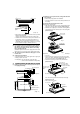
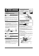
∗ 1 3/16 or more ∗ 1 3/16 or more (2) Make holes for suspension bolts, refrigerant and drain pipe, and wire. • Refer to the paper pattern for installation. • Select the location for each of holes and open the holes in the ceiling. (3) Remove the parts from the indoor unit. (3-1) Detach the suction grille. Required service space Air inlet • Slide the locking knobs (×2) on the suction grille inward (direction of arrows) and lift upwards. (Refer to Fig.
NOTE (ii) If it raises too much, a hook stops catching and falling out. Protection net (i) Hook • Use a hole-in anchor for existing ceilings, and a sunken insert, sunken anchor or other field supplied parts for new ceilings to reinforce the ceiling to bear the weight of the unit. Adjust clearance from the ceiling before proceeding further. Ceiling slab Anchor 1–2 3/16 Fig. 5 (3-3) Remove the rear metal plate for transmission wire, remote controller wire and refrigerant pipe.
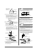
(5) When hanging the indoor unit main body, be sure to use a level or a plastic tube with water in it to make sure the drain piping is set either level or slightly tilted, in order to ensure proper drainage. (Refer to Fig. 12) A • Before refrigerant pipe work, check which type of refrigerant is used. Proper operation is not possible if the types of refrigerant are not the same. 6-2 CONNECTING THE REFRIGERANT PIPE 1˚ or less B 1˚ or less A.B 1˚ or less • The outdoor unit is charged with refrigerant.
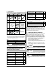
Table 3 Pipe size Recommended arm length of tool Further tightening angle (in.) (in.) φ3/8 60 to 90 degrees Approx. 7 7/8 φ5/8 30 to 60 degrees Approx. 11 13/16 After the work is finished, make sure to check that there is no gas leak.
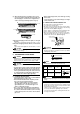
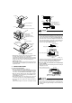
Good Top plate Tilt down Wrong Do not lift Make sure there is no slack Make sure it is not in the water Top penetration lid This hole not using it. Cut out Fig. 18 (A figure from an inside bottom) Fig. 21 CAUTION • Water accumulating in the drain piping can cause the drain to clog. Upward-facing refrigerant pipe L-shaped branch pipe kit (Optional accessories) Fig. 19 Thermistor lead line Top penetration lid clamp section • Be sure to use the drain pipe (1) and metal clamp (2).
• Keep in mind that it will become the cause of getting drain pipe blocked if water collects on drain pipe. 8. CAUTION 8-1 GENERAL INSTRUCTIONS • All field supplied parts and materials and electric works must conform to local codes. • Use copper wire only. • For electric wiring work, refer to also “Wiring diagram label” attached to the control box lid. • For remote controller wiring details, refer to the installation manual attached to the remote controller.
Refer to Fig. 27 Power supply teminal block (2P) Transmission Control box terminal block (6P) Ground terminal Remote controller wire and transmission wire Power supply wire • Use the specified electric wire. Connect the wire securely to the terminal. Lock the wire down without applying excessive force to the terminal. (Tightening torque: 0.
1. When using 1 remote controller for 1 indoor unit. (Normal operation) Power supply 208-230V Decoration panel Outdoor unit 60Hz Control box IN/D OUT/D F 1 F2 F1 F 2 L1 L 2 (ii) Protection net Hook (i) (ii) L1 L2 P1 P2 F1 F2 T1 T2 Indoor unit P1 P2 Remote controller Hook 2. When using 2 remote controllers for 1 indoor unit.
11-2 2 remote controllers control (Controlling 1 indoor unit by 2 remote controllers) • When using 2 remote controllers, one must be set to “MAIN” and the other to “SUB”. MAIN/SUB CHANGEOVER (1) Insert a screw driver into the recess between the upper and lower part of remote controller and, working from the 2 positions, pry off the upper part. The remote controller PC board is attached to the upper part of remote controller. (Refer to Fig.
If nothing is displayed in the remote controller, check the following items before attempting a diagnosis based on the malfunction code, as they might be a cause. • Disconnected or incorrect wiring (between power supply and the outdoor unit, between the outdoor and indoor units, and between the indoor unit and the remote controller) • Burnt out indoor or outdoor unit fuse • “ ” will be displayed for a few seconds on the remote controller immediately after the power is turned on.
Instantaneous overcurrent (outdoor) L5 Possible earth fault or short circuit in the compressor motor. Electric thermal (outdoor) L8 L9 Possible electrical overload in the compressor or cut line in the compressor motor. Stall prevention (outdoor) Compressor possibly locked.
3PN06240-2E EM04A051B (0510) FS