
Service Manual
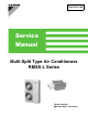


Table Of Contents
- Cover
- Table of contents
- Part 1 List of Functions
- Part 2 Specifications
- Part 3 Printed Circuit Board Connector Wiring Diagram
- Part 4 Refrigerant Circuit
- Part 5 Functions and Control
- Part 6 Test Operation and Field Settings
- Part 7 Remote Controller
- Part 8 Troubleshooting
- 1. Troubleshooting with LED
- 2. Service Diagnosis
- 3. Error Codes and Description
- 4. Troubleshooting for CTXG, CTXS, FTXS, CDXS, FDXS, FVXS Series
- 5. Troubleshooting for FFQ Series
- 6. Troubleshooting for Branch Provider (BP) Unit
- 7. Troubleshooting for Outdoor Unit
- 8. Thermistor Resistance/Temperature Characteristics
- 9. Pressure Sensor
- 10. Method of Replacing Inverter’s Power Transistors Modules
- Part 9 Appendix

SiUS181631EA
Table of Contents vi
7.17 Outdoor Unit PCB Abnormality................................................................. 245
7.18 Radiation Fin Temperature Rise .............................................................. 246
7.19 Inverter Compressor Abnormality............................................................. 247
7.20 Inverter Current Abnormality .................................................................... 248
7.21 Compressor Start-up Error ....................................................................... 249
7.22 High Voltage of Capacitor in Main Inverter Circuit ................................... 250
7.23 Radiation Fin Thermistor Abnormality ...................................................... 251
7.24 Low Pressure Drop due to Refrigerant Shortage or
Electronic Expansion Valve Abnormality.................................................. 252
7.25 Power Supply Insufficient or Instantaneous Failure ................................. 254
7.26 Check Operation is not Conducted .......................................................... 255
7.27 Signal Transmission Error between Indoor Unit and
Outdoor Unit in the Same System............................................................ 256
7.28 Excessive Number of Indoor Units ........................................................... 257
7.29 Address Duplication of Central Remote Controller................................... 258
7.30 Transmission Error between Centralized Remote Controller and
Indoor Unit................................................................................................ 259
7.31 System is not Set yet................................................................................ 261
7.32 System Abnormality, Refrigerant System Address Undefined ................. 262
7.33 Check for Outdoor Unit............................................................................. 263
8. Thermistor Resistance/Temperature Characteristics..............................267
9. Pressure Sensor .....................................................................................269
10.Method of Replacing Inverter’s Power Transistors Modules...................270
Part 9 Appendix............................................................................ 272
1. Piping Diagrams......................................................................................273
1.1 Outdoor Unit ............................................................................................. 273
1.2 Branch Provider (BP) Unit ........................................................................ 274
1.3 Indoor Unit................................................................................................ 275
2. Wiring Diagrams......................................................................................278
2.1 Outdoor Unit ............................................................................................. 278
2.2 Branch Provider (BP) Unit ........................................................................ 279
2.3 Indoor Unit................................................................................................ 280
3. Operation Limit........................................................................................287