
Service Manual
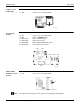
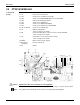
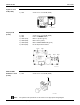


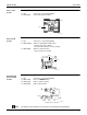


Table Of Contents
- Cover
- Table of contents
- Part 1 List of Functions
- Part 2 Specifications
- Part 3 Printed Circuit Board Connector Wiring Diagram
- Part 4 Refrigerant Circuit
- Part 5 Functions and Control
- Part 6 Test Operation and Field Settings
- Part 7 Remote Controller
- Part 8 Troubleshooting
- 1. Troubleshooting with LED
- 2. Service Diagnosis
- 3. Error Codes and Description
- 4. Troubleshooting for CTXG, CTXS, FTXS, CDXS, FDXS, FVXS Series
- 5. Troubleshooting for FFQ Series
- 6. Troubleshooting for Branch Provider (BP) Unit
- 7. Troubleshooting for Outdoor Unit
- 8. Thermistor Resistance/Temperature Characteristics
- 9. Pressure Sensor
- 10. Method of Replacing Inverter’s Power Transistors Modules
- Part 9 Appendix

SiUS181631EA Indoor Unit
Printed Circuit Board Connector Wiring Diagram 37
Sensor PCB
(PCB1)
Service PCB
(PCB3)
Display/Signal
Receiver PCB
(PCB4)
★
LED3 does not function.
Note: The symbols in the parenthesis are the names on the appropriate wiring diagram.
1) S49 Connector for control PCB (PCB2)
2) RTH2 (R1T) Room temperature thermistor
S49
RTH2
3P191450-1
1) S27 Connector for control PCB (PCB2)
2) SW2 (S2W)-4 Switch for upward airflow limit setting
∗
Refer to page 143 for details.
∗
Keep the other switches as factory setting.
3) SW4 (S4W) Switch for airflow selection
∗
Refer to page 76 for details.
S27
SW4
SW2-4
3P191448-1
1) S47 Connector for control PCB (PCB2)
2) SW1 (S1W) Indoor unit ON/OFF button
3) LED1 (H1P) LED for operation (green)
4) LED2 (H2P) LED for timer (yellow)
S47SW1LED2
LED1
3P191447-1