
Service Manual
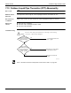
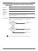

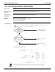

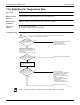


Table Of Contents
- Cover
- Table of contents
- Part 1 List of Functions
- Part 2 Specifications
- Part 3 Printed Circuit Board Connector Wiring Diagram
- Part 4 Refrigerant Circuit
- Part 5 Functions and Control
- Part 6 Test Operation and Field Settings
- Part 7 Remote Controller
- Part 8 Troubleshooting
- 1. Troubleshooting with LED
- 2. Service Diagnosis
- 3. Error Codes and Description
- 4. Troubleshooting for CTXG, CTXS, FTXS, CDXS, FDXS, FVXS Series
- 5. Troubleshooting for FFQ Series
- 6. Troubleshooting for Branch Provider (BP) Unit
- 7. Troubleshooting for Outdoor Unit
- 8. Thermistor Resistance/Temperature Characteristics
- 9. Pressure Sensor
- 10. Method of Replacing Inverter’s Power Transistors Modules
- Part 9 Appendix

Troubleshooting for Outdoor Unit SiUS181631EA
244 Troubleshooting
7.16 Low Pressure Sensor Abnormality
Error Code
JC
Method of Error
Detection
The pressure detected by low pressure sensor determines the error.
Error Decision
Conditions
When the low pressure sensor is short circuit or open circuit
Supposed
Causes
Defective low pressure sensor
Wrong connection with high pressure sensor
Defective main PCB (A1P)
Troubleshooting
∗
1: Voltage measurement point
For pressure/voltage characteristics graph, refer to Pressure Sensor on page 269.
Is the
low pressure
sensor connected to
X18A (blue) on the
main PCB
(A1P)?
Is the voltage normal
when measured between the
pins 2 and 3 of X18A?
(See ∗1)
Replace the low pressure
sensor.
(R23970)
Connect the low pressure
sensor and turn on again.
NO
Replace the main PCB
(A1P).
NO
YES
YES
Caution
Be sure to turn off the power switch before connecting or disconnecting
connectors, or parts may be damaged.
Main PCB (A1P)
X18A (Blue)
Red
Black
Low pressure sensor
White
(R13034)
Measure the voltage here.
Microcomputer
A/D input