
Service Manual
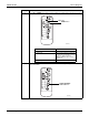
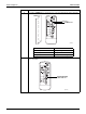

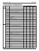

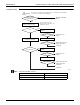


Table Of Contents
- Cover
- Table of contents
- Part 1 List of Functions
- Part 2 Specifications
- Part 3 Printed Circuit Board Connector Wiring Diagram
- Part 4 Refrigerant Circuit
- Part 5 Functions and Control
- Part 6 Test Operation and Field Settings
- Part 7 Remote Controller
- Part 8 Troubleshooting
- 1. Troubleshooting with LED
- 2. Service Diagnosis
- 3. Error Codes and Description
- 4. Troubleshooting for CTXG, CTXS, FTXS, CDXS, FDXS, FVXS Series
- 5. Troubleshooting for FFQ Series
- 6. Troubleshooting for Branch Provider (BP) Unit
- 7. Troubleshooting for Outdoor Unit
- 8. Thermistor Resistance/Temperature Characteristics
- 9. Pressure Sensor
- 10. Method of Replacing Inverter’s Power Transistors Modules
- Part 9 Appendix

SiUS181631EA Troubleshooting for CTXG, CTXS, FTXS, CDXS, FDXS, FVXS Series
Troubleshooting 197
Troubleshooting
Note: Check the following connector.
Check the connection of
connectors. (Refer to Note)
Correct the connection.
OK?
Check the power supply
voltage.
Start operation.
Voltage as rated?
Error repeats?
Check the power supply
voltage.
Start operation.
Voltage as rated?
Error repeats?
Error repeats?
Combination of
the indoor and outdoor
unit matched?
YES
NO
NO
YES
NO
NO
YES
(R23407)
Caution
∗ To secure the connection,
disconnect the connectors once
and then reconnect.
YES
NO
YES
NO
YES
NO
YES
Match the compatible
models.
Correct the power
supply.
Replace the indoor unit
PCB (control PCB).
Completed.
Completed.
Correct the power
supply.
Replace the indoor unit
PCB (control PCB).
Completed.
Be sure to turn off the power switch before connecting or disconnecting
connectors, or parts may be damaged.
Model Type Connector
CTXG, CTXS, FTXS, FVXS series Terminal strip ~ Control PCB (H1, H2, H3)
CDXS, FDXS series Terminal block ~ Control PCB (H1, H2, H3)