
Service Manual


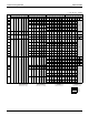
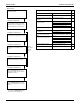
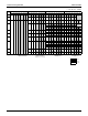
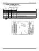
Table Of Contents
- Cover
- Table of contents
- Part 1 List of Functions
- Part 2 Specifications
- Part 3 Printed Circuit Board Connector Wiring Diagram
- Part 4 Refrigerant Circuit
- Part 5 Functions and Control
- Part 6 Test Operation and Field Settings
- Part 7 Remote Controller
- Part 8 Troubleshooting
- 1. Troubleshooting with LED
- 2. Service Diagnosis
- 3. Error Codes and Description
- 4. Troubleshooting for CTXG, CTXS, FTXS, CDXS, FDXS, FVXS Series
- 5. Troubleshooting for FFQ Series
- 6. Troubleshooting for Branch Provider (BP) Unit
- 7. Troubleshooting for Outdoor Unit
- 8. Thermistor Resistance/Temperature Characteristics
- 9. Pressure Sensor
- 10. Method of Replacing Inverter’s Power Transistors Modules
- Part 9 Appendix

SiUS181631EA Troubleshooting with LED
Troubleshooting 175
Error code indication in monitor mode
Selection of check item
Monitor mode
Confirmation of malfunction 1
Press MODE (BS1) button and enter
the monitor mode.
Press SET (BS2) button and select
a check item according to the LED
pattern of No.14~16 and No.20~22.
Refer to page 130 for check items.
Press RETURN (BS3) button once
to display the first digit of error code.
Confirmation of malfunction 2
Press SET (BS2) button once to
display the second digit of error
code.
Press RETURN (BS3) button and
return to the initial status of monitor
mode.
Confirmation of malfunction 3
Press SET (BS2) button once to
display the malfunction location.
Detail
description
on next
page.
Confirmation of malfunction 4
Press SET (BS2) button once to
display the malfunction unit and the
malfunction location.
∗ If you become unsure of how to
proceed, press MODE (BS1) button
and return to the setting mode 1.
Contents of malfunction
Error
code
Outdoor unit PCB abnormality Detection of DIII-Net
E1
Actuation of high pressure switch High pressure switch activated (S1PH) E3
Actuation of low pressure sensor Abnormal Pe E4
Compressor motor lock Detection of compressor lock E5
Outdoor fan motor abnormality Detection of fan motor lock (M1F) E7
Detection of fan motor lock (M2F)
Moving part of electronic expansion
valve (Y1E, Y3E) abnormality
Y1E (main) E9
Y3E (subcooling)
Outdoor temperature thermistor (R1T)
abnormality
Short or open circuit (R1T) H9
Discharge pipe temperature
abnormality
Abnormal Tdi F3
Refrigerant overcharged Refrigerant overcharge F6
Discharge pipe thermistor (R2T)
abnormality
Short or open circuit (R2T) J3
Suction pipe thermistor (R3T, R5T)
abnormality
Short or open circuit (suction 1: R3T) J5
Short or open circuit (suction 2: R5T)
Outdoor heat exchanger thermistor
(R4T) abnormality
Short or open circuit (R4T) J6
Outdoor liquid pipe thermistor (R7T)
abnormality
Short or open circuit (R7T) J7
Subcooling heat exchanger gas pipe
thermistor (R6T) abnormality
Short or open circuit (R6T) J9
High pressure sensor abnormality Short or open circuit (S1NPH) JA
Low pressure sensor abnormality Short or open circuit (S1NPL) JC
Outdoor unit PCB abnormality Faulty IPM L1
Abnormal current sensor offset
Abnormal IGBT
Faulty current sensor
Abnormal SP-PAM overvoltage
Radiation fin temperature rise Overheating (FINTH) L4
Inverter compressor abnormality Inverter instantaneous overcurrent L5
Inverter current abnormality Electronic thermal switch 1 L8
Electronic thermal switch 2
Out-of-step
Speed down after startup
Lightening detection
Compressor start-up error Stall prevention (Current increasing) L9
Stall prevention (Faulty start up)
Abnormal waveform in startup
Out-of-step