
Service Manual
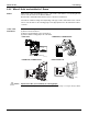

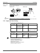

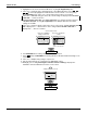


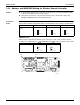

Table Of Contents
- Cover
- Table of contents
- Part 1 List of Functions
- Part 2 Specifications
- Part 3 Printed Circuit Board Connector Wiring Diagram
- Part 4 Refrigerant Circuit
- Part 5 Functions and Control
- Part 6 Test Operation and Field Settings
- Part 7 Remote Controller
- Part 8 Troubleshooting
- 1. Troubleshooting with LED
- 2. Service Diagnosis
- 3. Error Codes and Description
- 4. Troubleshooting for CTXG, CTXS, FTXS, CDXS, FDXS, FVXS Series
- 5. Troubleshooting for FFQ Series
- 6. Troubleshooting for Branch Provider (BP) Unit
- 7. Troubleshooting for Outdoor Unit
- 8. Thermistor Resistance/Temperature Characteristics
- 9. Pressure Sensor
- 10. Method of Replacing Inverter’s Power Transistors Modules
- Part 9 Appendix

Field Settings SiUS181631EA
144 Test Operation and Field Settings
2.3 FFQ Series
2.3.1 How to Change the Field Settings
Outline If optional accessories are mounted on the indoor unit, the indoor unit setting may have to be
changed. Refer to the instruction manual for each optional accessory.
Note: When using 2 remote controllers for 1 indoor unit, change the field settings from MAIN remote
controller. Note that the field settings can not be set from SUB remote controller.
Wired Remote
Controller
(BRC1E73)
a Unit No.
b First code No.
c Second code No.
d Mode
1. Press and hold Cancel button for 4 seconds or longer.
Service settings menu is displayed.
2. Select in the Service Settings menu, and press Menu/OK button.
Field settings screen is displayed.
a
b
c
d
(R18831)
<Basic screen>
1
Set temperature
28
˚C
Fan
ReturnPress the menu button
Press and hold Cancel
button for 4 seconds or
longer during backlight lit.
Field Settings
<Service settings menu screen>
2
Setting
1/3
Service Settings
Test Operation
Maintenance Contact
Field Settings
Energy Saving Options
Prohibit Function
Min Setpoints Differential
Press Menu/OK button.