
Service Manual
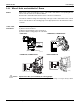

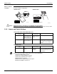

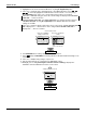


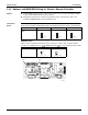

Table Of Contents
- Cover
- Table of contents
- Part 1 List of Functions
- Part 2 Specifications
- Part 3 Printed Circuit Board Connector Wiring Diagram
- Part 4 Refrigerant Circuit
- Part 5 Functions and Control
- Part 6 Test Operation and Field Settings
- Part 7 Remote Controller
- Part 8 Troubleshooting
- 1. Troubleshooting with LED
- 2. Service Diagnosis
- 3. Error Codes and Description
- 4. Troubleshooting for CTXG, CTXS, FTXS, CDXS, FDXS, FVXS Series
- 5. Troubleshooting for FFQ Series
- 6. Troubleshooting for Branch Provider (BP) Unit
- 7. Troubleshooting for Outdoor Unit
- 8. Thermistor Resistance/Temperature Characteristics
- 9. Pressure Sensor
- 10. Method of Replacing Inverter’s Power Transistors Modules
- Part 9 Appendix

SiUS181631EA Field Settings
Test Operation and Field Settings 141
2.2.3 When 2 Units are Installed in 1 Room
Outline When 2 indoor units are installed in 1 room, 1 of the 2 indoor units and the corresponding wireless
remote controller can be set for different address.
Both the indoor unit PCB and the wireless remote controller need alteration.
The method of address setting varies depending on the type of indoor unit and the series of wired
remote controller. Refer to the following pages for the appropriate indoor unit and wireless remote
controller.
CTXG, CTXS,
FTXS Series
(1) Remove the front grille.
(2) Remove the electrical box.
(3) Remove the shield plate of the electrical box.
(4) Cut the address setting jumper JA on the PCB.
Caution Replace the PCB if you accidentally cut a wrong jumper.
Jumpers are necessary for electronic circuit. Improper operation may occur if you cut any of them.
CTXG Series CTXS07JVJU, CTXS09/12HVJU
CTXS07LVJU, FTXS09/12LVJU FTXS15/18/24LVJU
JA
(Bottom of electrical box)
ADDRESS : JA
EXIST : 1
CUT : 2
(R21128)
Address
JA
JB
JC
Address
JA
EXIST
1
CUT 2
(R17414)
ADDRESS
JC
JA
JB
ADDRESS:JA
EXIST
1
CUT
2
(R17375)
(R9665)
ADDRESS
JC
JA
JB
ADDRESS:JA
EXIST
1
CUT
2